Volkswagen Golf / Golf GTI / Golf Variant. Service manual - part 673


  Index      Volkswagen     Volkswagen Golf / Golf GTI / Golf Variant - service and repair manual 2013 year


Search            copyright infringement  


Content   ..  671  672  673  674   ..


Volkswagen Golf / Golf GTI / Golf Variant. Service manual - part 673


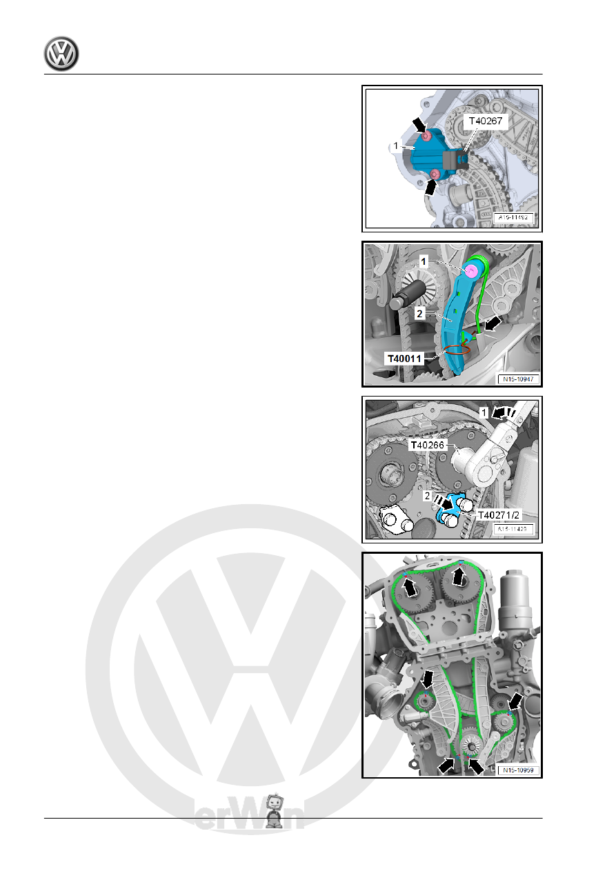
– Install the chain tensioner -1- and tighten the bolts -arrows-.

– Install the chain tensioner -2-. The wire clip -arrow- must come

in to contact with the oil pan upper section opening. Tighten

the bolt -1- and remove the Locking Pin (3 pc.) - T40011- .

– Turn the intake camshaft in the direction of the arrow -1- using

the Adapter - T40266- until the Camshaft Lock - T40271/2-

-2- can be pushed out of the chain sprocket splines. Release

the camshaft.

– Remove the Camshaft Lock - Component 1 - T40271/1- and

Camshaft Lock - Component 2 - T40271/2- .

– Check the adjustment. The painted chain links -arrows- must

line up with the markings on the chain sprockets.

– Install the bolts -arrows- and tighten them. Tightening specifi‐

cation. Refer to -item 4- 

⇒ Item 4 (page 91)

 .

– Lubricate the holes -arrows- with engine oil.

Note

Adapter sleeve -1- is not present on every bearing bracket.

– Attach the bearing mount. Do not tilt it when doing this. Hand-

tighten the bolts -arrows-.

– Remove the Tensioner Locking Tool - T40267- .
– Tighten the bearing bracket bolts -item 5-

⇒ Item 5 (page 115)

 .

– Install the pilot valves -item 6- 

⇒ Item 7 (page 115)

 .

– Let the engine turn a second time in the direction of engine

rotation.

Note

Due to the ratio, the painted chain links no longer match up after

the engine has been turned.

– Remove the turning over tool and install the lower timing chain

cover. Refer to 

⇒ page 109

 .

Note

Tighten the bolts -1 and 4- with an additional turn after installing

the vibration damper. The bolts must be removed again to install

the vibration damper.

– Install the vibration damper. Refer to

⇒ “1.4 Vibration Damper, Removing and Installing”, page 47

 .

– Install the upper timing chain cover. Refer to

⇒ “2.2.1 Upper Timing Chain Cover, Removing and Installing”,

page 106

 .

– Install the ribbed belt tensioning damper. Refer to

⇒ “1.3 Ribbed Belt Tensioner, Removing and Installing”, page

47

 .

– Install the ribbed belt. Refer to

⇒ “1.2 Ribbed Belt, Removing and Installing”, page 46

 .

The rest of the installation is performed in reverse order of re‐

moval, noting the following:
– After performing work on the chain drive the adaptation value

in the Engine Control Module (ECM) must be adapted. To do

this turn on the ignition and select the following menu items on

the Vehicle Diagnostic Tester :

01 - Engine Electronics

Guided Functions

01 - Adaptation After Repair Work On the Chain

Drive

Tightening Specifications
♦ Refer to

⇒ “3.1 Overview - Camshaft Timing Chain”, page 114

 .

♦ Refer to

⇒ “3.2 Overview - Balance Shaft Drive Chain”, page 116

 .

♦ Refer to ⇒  Body Exterior; Rep. Gr.  66 ; Noise Insulation;

Overview - Noise Insulation .

3.4

Balance Shaft Drive Chain, Removing

and Installing

The procedure “Balance shaft drive chain removing and installing”

is in the “Camshaft timing chain removing and installing” proce‐

dure. Refer to

⇒ “3.3 Camshaft Timing Chain, Removing and Installing”,

page 118

 .

3.5

Chain Length, Checking

Caution

This procedure contains mandatory replaceable parts. Refer

to component overview prior to starting procedure.

Mandatory Replacement Parts
♦ Plug - Lower Timing Chain Cover

Note

If due to complaints (for example noises) an elongated camshaft

timing chain is suspected, the chain length can be checked as

described as follows.

– Remove the plug -arrow-. The plugs must be replaced.

– Turn the vibration damper in direction of engine rotation until

the chain tensioner piston is maximally driven out in direction

of -arrow-.

– Count the visible piston threads.

Note

The visible threads are all of the threads that are located to the

right of the chain tensioner housing -arrow-.

♦ If six or fewer threads are visible: the camshaft timing chain

does not need to be replaced.

♦ If seven or more threads are visible: the camshaft timing chain

must be replaced. Refer to

⇒ “3.3 Camshaft Timing Chain, Removing and Installing”,

page 118

 .

3.6

Valve Timing, Checking

Special tools and workshop equipment required
♦ Dial Gauge Set - VAS6341-
♦ Dial Gauge Adapter - T10170A-
– Remove timing chain upper cover. Refer to

⇒ “2.2.1 Upper Timing Chain Cover, Removing and Installing”,

page 106

 .

– Remove the noise insulation. Refer to ⇒  Body Exterior; Rep.

Gr.  66 ; Noise Insulation; Overview - Noise Insulation .


Content   ..  671  672  673  674   ..