Volkswagen Golf / Golf GTI / Golf Variant. Service manual - part 671


  Index      Volkswagen     Volkswagen Golf / Golf GTI / Golf Variant - service and repair manual 2013 year


Search            copyright infringement  


Content   ..  669  670  671  672   ..


Volkswagen Golf / Golf GTI / Golf Variant. Service manual - part 671


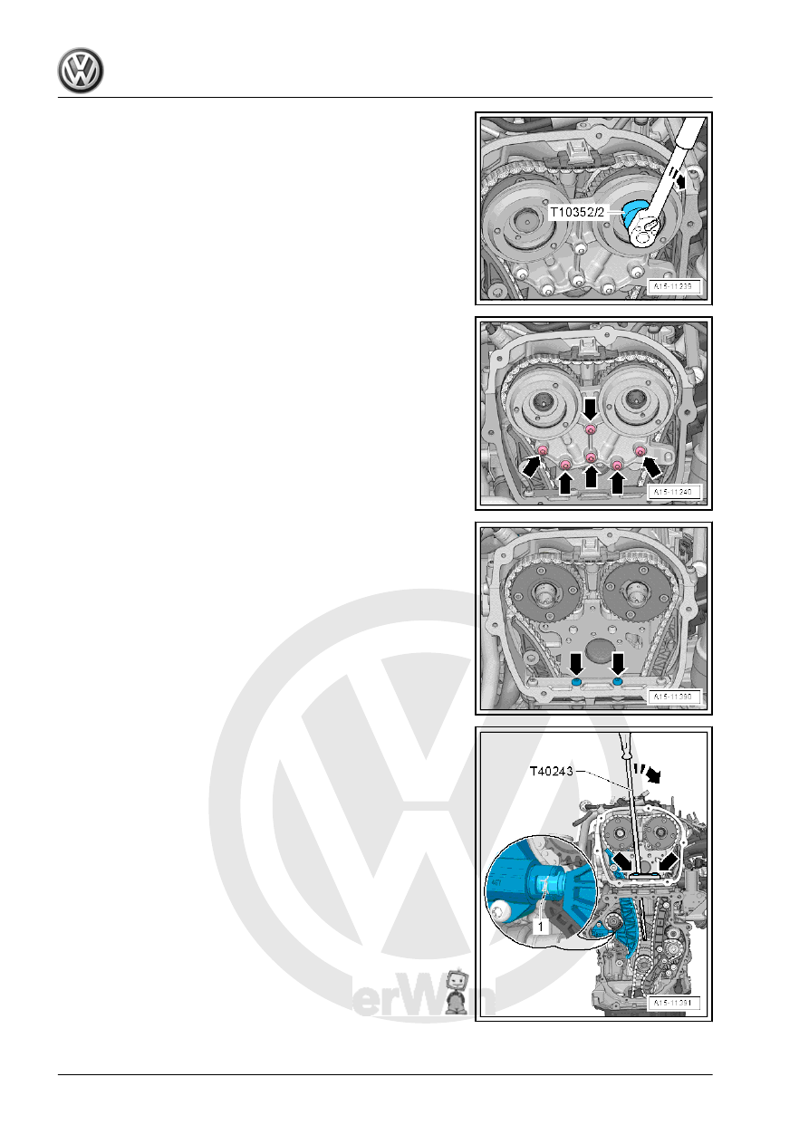
– Remove the left and right pilot valves using the Assembly Tool

- T10352/2- in the direction of the -arrow-.

– Remove the bolts -arrows- and remove the bearing bracket.

– Remove the bolts -arrows-.

– Install the Chain Tensioner Lever - T40243- in direction of

-arrows-.

– Press the chain tensioner locking ring -1- together and hold it.
– Slowly press and hold the Chain Tensioner Lever - T40243-

in the direction of -arrow-.

– Secure the chain tensioner with the Tensioner Locking Tool -

T40267- .

– Remove the Chain Tensioner Lever - T40243- .

– Bolt the Camshaft Lock - Component 2 - T40271/2- to the cyl‐

inder head and slide into the splines on the chain sprocket in

the direction of the -arrow 2-. Rotate the intake camshaft with

the Adapter - T40266- -1- if necessary.

– Install the Camshaft Lock - Component 1 - T40271/1- on the

cylinder head.

For the following steps a second technician is necessity.

– Hold the exhaust camshaft with the Adapter - T40266- in the

direction of the -arrow A-. Remove the bolt -1- and guide the

tensioning rail -2- downward. Turn the camshaft clockwise in

direction of -arrow A- until the Camshaft Lock - Component 1

- T40271/1- can be pushed in the chain sprocket splines -C-.

– Remove the guide rail -1- by unlocking the latch -arrow- with

a screwdriver and pushing the guide rail forward.

– Remove the bolts -arrows- and remove the chain tensioner

-1-.

– Press the oil pump chain tensioner bracket in direction of

-arrow- and lock with Locking Pin (3 pc.) - T40011- .

– Remove the bolt -1- and remove the chain tensioner.

– Remove the bolts -1- and remove the glide rail -2-.

– Remove the camshaft timing chain from the camshaft sprocket

and hang it on the camshaft pins -arrows-.

– Remove the chain tensioner -1- for the balance shaft timing

chain.

– Remove the bolts -1-. Remove the tensioning rail -2- and the

glide rails -3 and 4-.

– Loosen the adjusting bolt -A- and remove the tensioning pin

-B-.

– Remove the oil pump drive timing chain to remove the three

stage chain sprocket.

– Remove the camshaft timing chain and drive chain for the bal‐

ance shaft.

Installing
– Check that the crankshaft is at Top Dead Center (TDC). The

flat area on the crankshaft -arrow- must be horizontal.

– Draw the markings on the cylinder block -1-, as shown, with a

waterproof marker.


Content   ..  669  670  671  672   ..