Volkswagen Golf / Golf GTI / Golf Variant. Service manual - part 657


  Index      Volkswagen     Volkswagen Golf / Golf GTI / Golf Variant - service and repair manual 2013 year


Search            copyright infringement  


Content   ..  655  656  657  658   ..


Volkswagen Golf / Golf GTI / Golf Variant. Service manual - part 657


3.2

Crankshaft Dimensions

(Dimensions in mm)

Reconditioning

Dimension 

1)

Crankshaft Bearing

Pin Diameter

Connecting Rod

Bearing Pin Diame‐

ter

Basic dimension

58.00


47.80

1)

 The preparation of worn crankshafts is not provided.

3.3

Main Bearing Shells Allocation

The bearing shells are allocated to the cylinder block with the

correct thickness at the factory. Colored spots serve to identify

the bearing thicknesses.
The code letters on the lower contact surface or on the top of the

cylinder block identify which bearing shell and where it must be

mounted on the cylinder block (upper bearing shell).
The code letters on the crankshaft identify which bearing shells

and where they must be installed in the bearing cover (lower

bearing shell).
The first letter is for bearing cover one, the second for bearing

cover two, etc.
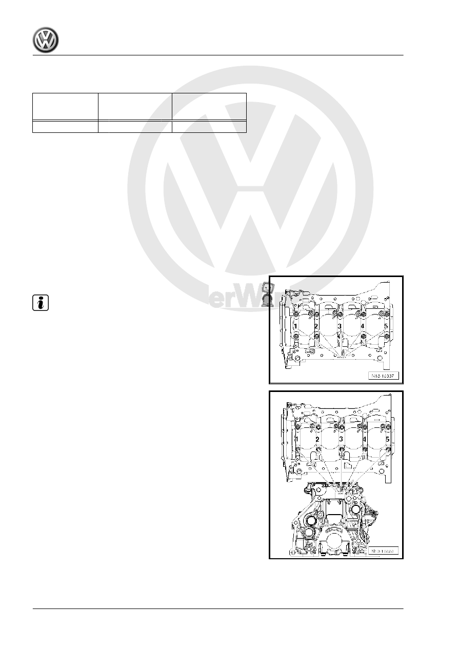
Cylinder Block Bearing Shell Identification:

Note

The cylinder block identification may be located either on the oil

pan sealing surface or on the top (transmission side) of the cyl‐

inder block.

The identification on the cylinder block is for the upper bearing

shell.

– Write down the letters and then use the table to find the color

identification.

Bearing Cap Bearing Shell Identification:
The identification on the crankshaft is for the lower bearing shell.
– Write down the letters and then use the table to find the color

identification.

S

=

Black

R

=

Red

G

=

Yellow

B

=

Blue

W

=

White

3.4

Crankshaft Needle Bearing, Replacing

Only for Vehicles Equipped with a Twin Clutch Transmission
Special tools and workshop equipment required
♦ Counter-support for example Puller - Kukko Counterstay -

22/1-

♦ Internal puller, for example Puller - Kukko Internal - 14-19mm

- 21/2-

♦ Bearing Installer - Bearing Press Piece - VW207C-

Caution

This procedure contains mandatory replaceable parts. Refer

to component overview prior to starting procedure.

Mandatory Replacement Parts
♦ Bearing - Crankshaft Needle
Conditions
• Always replace the needle bearing -arrow- after the engine

and transmission are separated.

• The front edges of the internal puller must not be broken off.

Remove Needle Bearing
– Remove the needle bearing -1- from the crankshaft -2- using

a standard internal puller such as the Puller - Kukko Internal -

14-19mm - 21/2- and counter support Puller - Kukko Counter‐

stay - 22/1- .

– The internal puller must be positioned behind the needle ring

-arrow-.

Installing
– Clean the bearing seat in the crankshaft and thinly coat with

grease.

– Drive the needle bearing into the crankshaft up to the instal‐

lation depth using the Bearing Installer - Bearing Press Piece

- VW207C- .

Installation Depth Dimension -a- = 2.0 mm

Note

If the needle bearing was unintentionally pushed in too deeply, it

must be replaced, because it will be damaged when it is removed

again.

3.5

Crankshaft, Measuring Axial Clearance

Special tools and workshop equipment required
♦ Dial Gauge Holder - VW387-
♦ Dial Gauge - 0-10mm - VAS6079-
Procedure
– Attach the Dial Gauge - 0-10mm - VAS6079- with the Dial

Gauge Holder - VW387- to the cylinder block and with ap‐

proximately 2 mm tension, set indicator against crankshaft

counterweight.

– Push the crankshaft against the dial gauge by hand and set

the dial gauge to “0”.

– Remove the crankshaft from the dial gauge and read the

measurement.

Axial clearance:
• New: 0.07 to 0.23 mm.
• Wear limit: 0.30 mm.

3.6

Crankshaft, Measuring Radial Clear‐

ance

Special tools and workshop equipment required
♦ Plastigage

®

Procedure

Note

Do not interchange used bearings

Bearing shells that are worn down to the nickel layer must be

replaced.

– Remove the crankshaft bearing cap and clean the bearing cap

and pins.

– Place Plastigage

®

 over entire width of bearing journal or into

bearing shells.

• Plastigage

®

 must rest in center of bearing shell.


Content   ..  655  656  657  658   ..