Volkswagen Golf / Golf GTI / Golf Variant. Service manual - part 564
Continuation for All
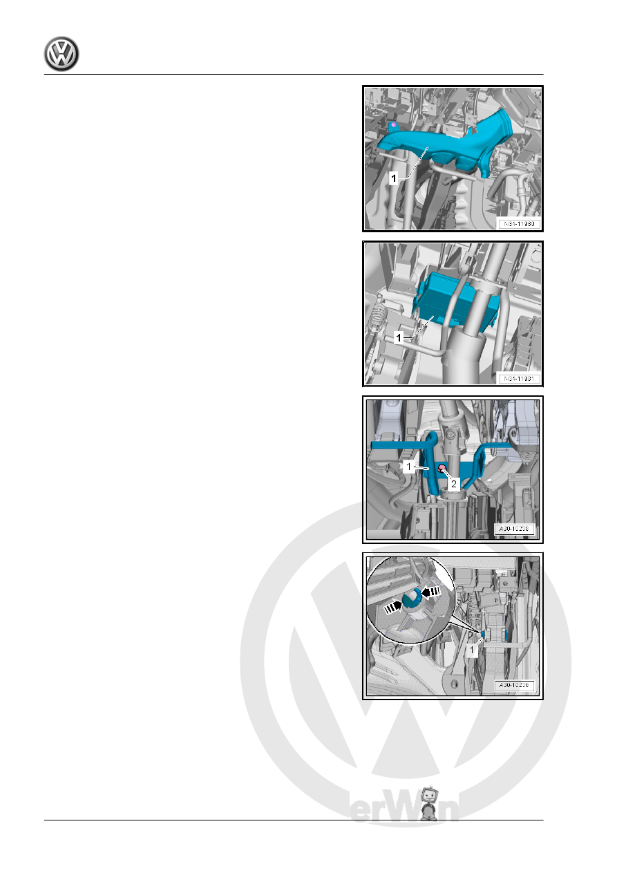
– Remove driver side footwell vent -1-. Refer to ⇒ Heating,
Ventilation and Air Conditioning; Rep. Gr. 87 ; Air Routing;
Driver Side Footwell Vent, Removing and Installing .
– Remove the Data Bus on Board Diagnostic Interface - J533-
-1- from the bracket. Refer to ⇒ Electrical Equipment; Rep.
Gr. 97 ; Control Modules; Component Location Overview -
Control Modules and push it aside.
– Remove bolt -2-, unclip the crash bolster -1- and push aside.
– Press the retainers together in direction of -arrows- and re‐
move the mounting pin -1- for the valve lifter/clutch master
cylinder to the right.