Volkswagen Golf / Golf GTI / Golf Variant. Service manual - part 562


  Index      Volkswagen     Volkswagen Golf / Golf GTI / Golf Variant - service and repair manual 2013 year


Search            copyright infringement  


Content   ..  560  561  562  563   ..


Volkswagen Golf / Golf GTI / Golf Variant. Service manual - part 562


❑ Seals/O-rings suitable for the line connection material. Refer to

⇒ Fig. ““Sealing Rings/O-Rings for Hose/Line Assembly or Pipe”“ , page 16

❑ Allocation. Refer to the Parts Catalog.

13 - Clamp

❑ The clamp must be removed in order to remove/install the hose/line assembly

14 - Clutch Slave Cylinder

❑ Removing and installing. Refer to 

⇒ “1.11 Clutch Slave Cylinder, Removing and Installing”, page 30

 .

Disconnect and Connect Clutch Mechanism Wires
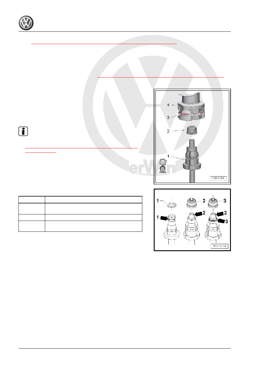
Separating
– Open the clip -3- with a screwdriver and remove the hose/line

assembly -1- from the connection -4-.

Connecting

Note

An O-ring can also be installed instead of a seal -2-. Refer to

⇒ Fig. ““Sealing Rings/O-Rings for Hose/Line Assembly or

Pipe”“ , page 16

 .

Replace the damaged seal -2-.

– Press in the hose/line assembly -1- at the connection -4- until

the clip -3- engages audibly.

– Pull on the hose/line assembly to make sure it is secure.

Sealing Rings/O-Rings for Hose/Line Assembly or Pipe

Item

Line Connection Version

1

Line connection with a groove all the way around

-arrow 1-

2

Line connection with a shoulder -arrow 2-

3

Line connection with a shoulder -arrow 2- and with

a groove all the way around -arrow 3-

• The seal / O-ring must be installed in the groove -arrow 1- and

-arrow 3-.

1.3.2

Overview - Clutch Hydraulics, RHD

1 - Clutch Slave Cylinder

❑ Removing and Instal‐

ling. Refer to

⇒ “1.11 Clutch Slave

Cylinder, Removing and

Installing”, page 30

 .

2 - Bleed Valve

❑ Bleed clutch mecha‐

nism. Refer to

⇒ “1.13 Clutch Mecha‐

nism, Bleeding”,

page 33

 .

❑ 4.5 Nm

3 - Dust Cap
4 - Supply Hose
5 - Brake Fluid Reservoir
6 - Seals

❑ must be located inside

the supply hose.

7 - Clutch Master Cylinder

❑ Removing and Instal‐

ling. Refer to

⇒ “1.10 Clutch Master

Cylinder, Removing and

Installing”, page 29

 .

8 - Clamp

❑ The clamp must be re‐

moved in order to re‐

move/install the hose/

line assembly

9 - Seal/O-Ring

❑ Replace if damaged
❑ Install on the line connection
❑ Install with brake fluid
❑ Seals/O-rings suitable for the line connection material

⇒ Fig. ““Sealing Rings/O-Rings for Hose/Line Assembly or Pipe”“ , page 16

❑ Allocation. Refer to the Parts Catalog.

10 - Bracket

❑ For hose/line assembly

11 - Hose/Line Assembly

❑ Allocation. Refer to the Parts Catalog.
❑ Removing and Installing. Refer to

⇒ “1.12 Clutch Mechanism Lines, Removing and Installing”, page 31

 .

12 - Seal/O-Ring

❑ Replace if damaged
❑ Install on the line connection
❑ Install with brake fluid
❑ Seals/O-rings suitable for the line connection material

⇒ Fig. ““Sealing Rings/O-Rings for Hose/Line Assembly or Pipe”“ , page 16

❑ Allocation. Refer to the Parts Catalog.

13 - Clamp

❑ The clamp must be removed in order to remove/install the hose/line assembly

14 - Hex bolt

❑ Tightening specification. Refer to 

⇒ “1.4 Overview - Clutch Release Mechanism”, page 18

 .

1.4

Overview - Clutch Release Mechanism

1 - Transmission
2 - Ball Stud

❑ 25 Nm
❑ For removing and instal‐

ling, remove the trans‐

mission

❑ Remove grease from

extractor lever contact

surfaces

❑ Grease the contact sur‐

face on the ball stud with

Grease for Clutch Disc

Shaft Splines -

G 000 100-

3 - Input Shaft Seal

❑ Replacing. Refer to

⇒ “1.4 Input Shaft Seal,

Replacing”, page 152

 .

4 - Guide Sleeve

❑ For removing and instal‐

ling, remove the trans‐

mission

❑ With vulcanized O-ring
❑ Replace the guide

sleeve and O-ring if the

O-ring is damaged.

5 - Spring

❑ For removing and instal‐

ling, remove the trans‐

mission

❑ Attach to the clutch re‐

lease lever

6 - Cylinder Bolt

❑ 20 Nm

7 - Clutch Release Lever

❑ For removing and installing, remove the transmission
❑ Remove and install together with release bearing

⇒ Fig. ““Remove and Install the Clutch Release Lever with the Release Bearing”“ , page 35

❑ Remove grease already present
❑ Grease the contact surface on the ball stud with Grease for Clutch Disc Shaft Splines - G 000 100-

8 - Release Bearing

❑ For removing and installing, remove the transmission
❑ Do not wash the bearing, just wipe it off.
❑ Replace loud bearings

❑ Removing from and installing in the clutch release lever

⇒ Fig. ““Removing and Installing the Release Bearing”“ , page 35

❑ Lubricate release lever contact surface with MoS 2 grease

9 - Hex Bolt

❑ 20 Nm

10 - Clutch Slave Cylinder

❑ Removing and installing. Refer to 

⇒ “1.11 Clutch Slave Cylinder, Removing and Installing”, page 30

 .

11 - Plunger
12 - Bolt

❑ Secures the clutch release lever when installing transmission
❑ Remove after installing the transmission
❑ Use an M8 x 35 bolt if the assembly bolt is missing.

1.5

Clutch Pedal, Removing and Installing

Removing
– Move the driver seat as far back as possible.
– Position the steering wheel as far upward as possible.
– If installed near bracket: remove the bracket -arrow- with the

Parking Aid Control Module - J446- . Refer to ⇒  Electrical

Equipment; Rep. Gr.  94 ; Parking Aid; Overview - Parking Aid

and push aside.

– Remove the return spring. (Refer to

⇒ “1.8 Return Spring, Removing and Installing”, page 23

 .)

or remove the over-center spring. Refer to

⇒ “1.7 Over-Center Spring, Removing and Installing”,

page 21

 .

Remove the Clutch Pedal Bearing Axle as Follows:
-1- = 14 mm internal socket wrench
A 14 mm hex socket wrench can also be used instead of a 14 mm

internal socket wrench.
• The clutch pedal bearing axle needs to be turned all the way

to the left, in direction of -arrow-.

The Brackets -A- will be Damaged.
– Move the clutch pedal a little so that the bearing axle can be

removed.


Content   ..  560  561  562  563   ..