Volkswagen Golf / Golf GTI / Golf Variant. Service manual - part 506


  Index      Volkswagen     Volkswagen Golf / Golf GTI / Golf Variant - service and repair manual 2013 year


Search            copyright infringement  


Content   ..  504  505  506  507   ..


Volkswagen Golf / Golf GTI / Golf Variant. Service manual - part 506


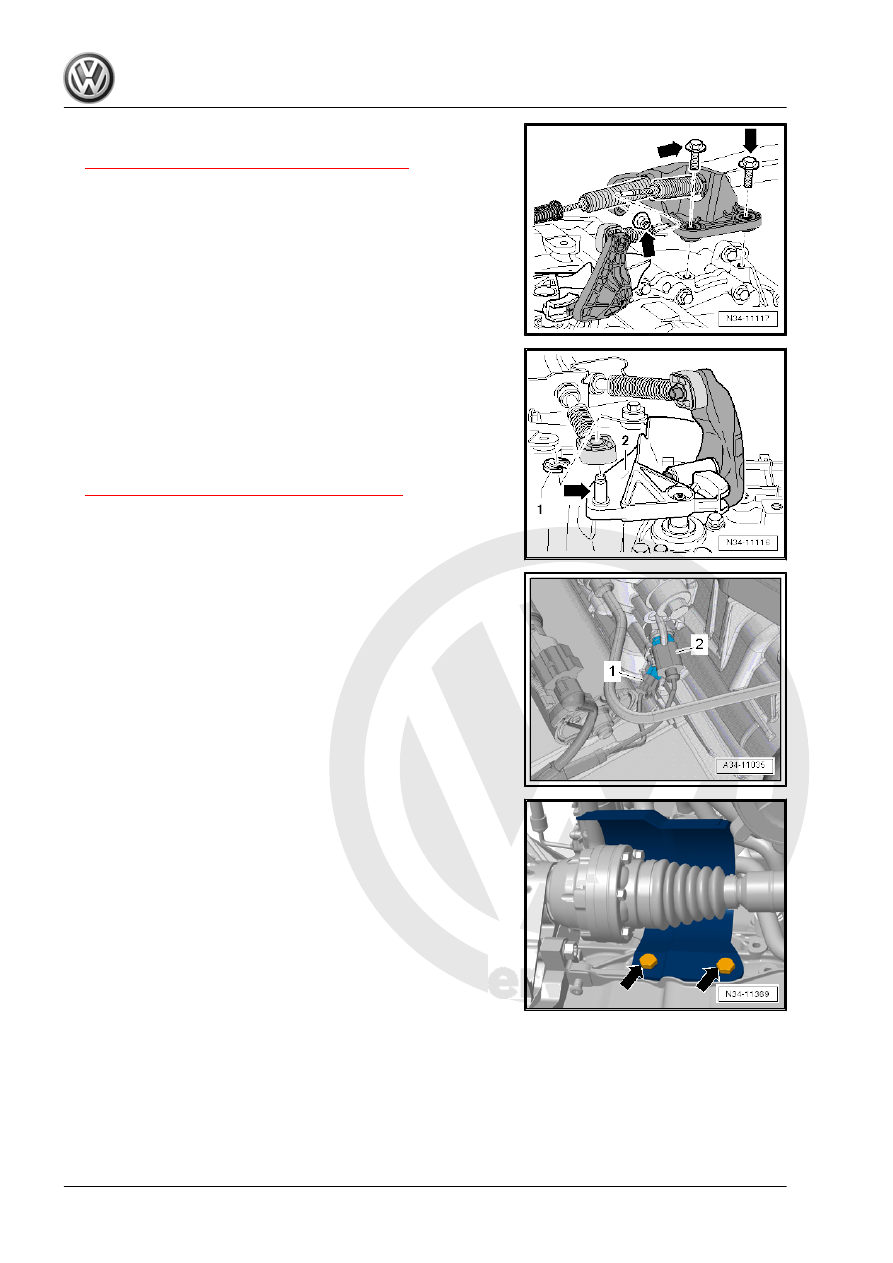
– Mount the cable bracket on the transmission and tighten the

bolts and nuts -arrows-. Refer to

⇒ “1.2 Overview - Selector Mechanism”, page 60

 .

– Install the selector cable in the cable retainer.
– Apply a small amount of grease on the pins -arrow- for the shift

lever -2-.

Grease allocation. Refer to the Parts Catalog.
– Replace the lock washer -1- each time it is removed.
– Adjust the shift lever mechanism. Refer to

⇒ “1.6 Selector Mechanism, Adjusting”, page 71

 .

– Install the starter. Refer to ⇒  Electrical Equipment; Rep. Gr. 

27 ; Starter; Starter, Removing and Installing .

– Connect the front left connectors to the transmission:
1 - Transmission for vehicles with start/stop system: Transmis‐

sion Neutral Position Sensor - G701-

2 - Back-Up Lamp Switch - F4-
– Install the drive axles. Refer to ⇒  Suspension, Wheels, Steer‐

ing; Rep. Gr.  40 ; Drive Axle; Drive Axle, Removing and

Installing .

– Install the drive axle heat shield (if equipped). Refer to ⇒  Sus‐

pension, Wheels, Steering; Rep. Gr.  40 ; Drive Axle; Drive

Axle Heat Shield, Removing and Installing .

– Assemble the exhaust system. Refer to ⇒  Engine Mechanical,

Fuel Injection and Ignition; Rep. Gr.  26 ; Exhaust Pipes/Muf‐

flers; Overview - Muffler .

– Install the subframe together with pendulum support. Refer to

⇒  Engine Mechanical, Fuel Injection and Ignition; Rep. Gr. 

10 ; Subframe Mount; Overview - Subframe Mount .

Note

Threaded inserts (for example, “Heli Coil”) are found in the pen‐

dulum support fastening holes on some transmissions. Refer to

⇒ Fig. ““Transmission with Threaded Insert (for example Heli Coil)

for Attaching the Pendulum Support”“ , page 107

 .

– Install pendulum support with new bolts. Refer to ⇒  Engine

Mechanical, Fuel Injection and Ignition; Rep. Gr.  10 ; Sub‐

frame Mount; Overview - Subframe Mount .

– Connect the connector -1- to the Oil Level Thermal Sensor -

G266- .

– Gear oil level in manual transmission, checking. Refer to

⇒ “8.1 Transmission Fluid Level, Checking”, page 142

 .

– If unclipped, carefully clip in the A/C system pipe and do not

disconnect the line system. Refer to ⇒  Heating, Ventilation

and Air Conditioning; Rep. Gr.  87 ; Refrigerant Circuit; System

Overview - Refrigerant Circuit .

– Install fuel filter. Do not open the line system. Refer to ⇒  Fuel

Supply System; Rep. Gr.  20 ; Fuel Delivery Unit/Fuel Level

Sensor; Overview - Fuel Delivery Unit/Fuel Level Sensor .

– Install the battery tray, battery and the battery cover. Refer to

⇒  Electrical Equipment; Rep. Gr.  27 ; Battery; Battery Tray,

Removing and Installing .

– Install the air filter housing. Refer to ⇒  Engine Mechanical,

Fuel Injection and Ignition; Rep. Gr.  24 ; Air Filter; Air Filter

Housing, Removing and Installing .

– Install the engine cover. Refer to ⇒  Rep. Gr.  10 ; Engine

Cover; Engine Cover, Removing and Installing .

– Install the plenum chamber cover. Refer to ⇒  Body Exterior;

Rep. Gr.  50 ; Bulkhead; Plenum Chamber Cover, Removing

and Installing .

– Install the windshield wiper arms. Refer to ⇒  Electrical Equip‐

ment; Rep. Gr.  92 ; Windshield Wiper System; Windshield

Wiper Arms, Removing and Installing .

– Install the lower section of the left front wheel housing liner.

Refer to ⇒  Body Exterior; Rep. Gr.  66 ; Wheel Housing Liner;

Front Wheel Housing Liner, Removing and Installing .

– Install the noise insulation. Refer to ⇒  Body Exterior; Rep. Gr. 

66 ; Noise Insulation; Overview - Noise Insulation .

2.2.2

Transmission, Installing, Vehicles with

Gasoline Engine

Special tools and workshop equipment required
♦ Transmission Support - 3282-
♦ Transmission Support - Mounting Plate 33 - 3282/33-
♦ Transmission Support - Pins 29 - 3282/29- .
♦ Engine and Gearbox Jack - VAS6931- .
♦ Slide Hammer Set - Adapter 40 - VW771/40-
♦ Engine Support Bridge - 10-222A-

♦ Hose Clamp up to 25mm - 3094-

Caution

This procedure contains mandatory replaceable parts. Refer

to component overview prior to starting procedure.

Mandatory Replacement Parts
♦ Nut - Selector Lever to Shift Lever Shaft with Shift Lever Cover
♦ Lock Washer - Cable Retainer to Selector Lever
♦ Lock Washer - Cable Mounting Bracket to Cable Retainer
♦ Bolt - Pendulum Support to Transmission
♦ Bolt - Transmission Bracket to Transmission

Note

Refer to “Transmission, Removing” to get a list of the special

tools needed. Refer to

⇒ “2.1.2 Transmission, Removing, Vehicles with Gasoline En‐

gine”, page 83

 .

Replace self-locking nuts and bolts after removing them.

Replace bolts that were tightened with an additional turn after

removing them.

Reinstall all cable ties that were loosened or cut off during re‐

moval at the same locations during installation.

Clean the input shaft splines and (on used clutch plates) the

hub splines. Remove any corrosion and then apply a very thin

coat of Grease for Clutch Disc Shaft Splines - G 000 100- on

the splines. Then move the clutch plate back and forth on the

input shaft until the hub moves freely on the shaft. Excess

grease must be removed.

– If the transmission is replaced, replace the gearshift lever and

the relay lever.

– Use a thread cutter to carefully clean all threaded holes con‐

taining self-locking bolts to remove any locking compound

residue.

– The alignment sleeves for centering the engine/transmission

must be present inside the cylinder block. Install them if they

are missing.

If the alignment sleeves are missing, it will be difficult to shift, there

will be clutch problems and the transmission may make noises

(loose rattling).

Engage the intermediate plate on the sealing flange and push it

onto the alignment sleeves -arrows-.
– Check the release bearing for wear. Replace the clutch slave

cylinder with release bearing if necessary. Refer to

⇒ “1.11 Clutch Slave Cylinder with Release Bearing, Remov‐

ing and Installing”, page 33

 .

Align the -3282- with the -3282/33- in order to install the trans‐

mission.
– Align the arms of the Transmission Support so that they match

up with the holes in the Adjustment Plate .

– Install the Support Elements -A- as illustrated on the Adjust‐

ment Plate .

– Install the Mounting Element -C- instead of the -3282/29- .
– Place the transmission on the -VAS6931- .
– Align the Adjustment Plate so that it is parallel to the trans‐

mission.

– Install the -3282/29- into the rear hole in the transmission for

the pendulum support bolt.

– Secure the -VW771/40- in the threaded hole of the transmis‐

sion housing as illustrated.

– Secure the transmission on the -3282- using the bolt (M10×20)

-A-.

The drift -B- must be flush at the bottom with the guide on the

-3282- -arrow-.
– Position the -VAS6931- under the vehicle. The arrow on the

adjusting plate points in direction of travel.

Note

Pay attention to the lines when installing the transmission.

– Turn the transmission in direction of -arrow- near the differen‐

tial via the spindles on the -3282- .

– Lift the transmission carefully.
– Move the transmission using the spindles of the -3282- into an

angled position.

– Push the engine toward the front a little bit (a second techni‐

cian is needed).


Content   ..  504  505  506  507   ..