Volkswagen Golf / Golf GTI / Golf Variant. Service manual - part 505


  Index      Volkswagen     Volkswagen Golf / Golf GTI / Golf Variant - service and repair manual 2013 year


Search            copyright infringement  


Content   ..  503  504  505  506   ..


Volkswagen Golf / Golf GTI / Golf Variant. Service manual - part 505


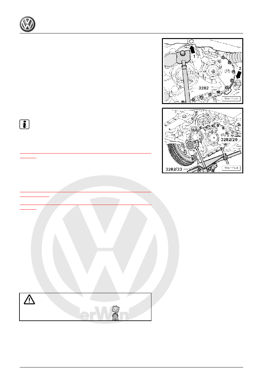
– Guide the transmission and the differential over the subframe

and swing them out.

– Be careful of the longitudinal member -arrow 1- and of the

subframe -arrow 2-.

– Move the transmission higher than the differential if necessa‐

ry.

– Carefully lower the transmission.

Note

Pay attention to the lines when lowering the transmission.

Install the transmission. Refer to

⇒ “2.2.2 Transmission, Installing, Vehicles with Gasoline Engine”,

page 97

2.2

Transmission, Installing

⇒ “2.2.1 Transmission, Installing, Vehicles with Turbo Diesel En‐

gine”, page 92
⇒ “2.2.2 Transmission, Installing, Vehicles with Gasoline Engine”,

page 97

2.2.1

Transmission, Installing, Vehicles with

Turbo Diesel Engine

Special tools and workshop equipment required
♦ Transmission Support - 3282-
♦ Transmission Support - Pins 29 - 3282/29-
♦ Transmission Support - Mounting Plate 33 - 3282/33-
♦ Engine and Gearbox Jack - VAS6931-
♦ Slide Hammer Set - Adapter 40 - VW771/40-
♦ Engine Support Bridge - 10-222A-
♦ Hose Clamp up to 25mm - 3094-

Caution

This procedure contains mandatory replaceable parts. Refer

to component overview prior to starting procedure.

Mandatory Replacement Parts
♦ Nut - Selector Lever to Shift Lever Shaft with Shift Lever Cover
♦ Lock Washer - Cable Retainer to Selector Lever
♦ Lock Washer - Cable Mounting Bracket to Cable Retainer

♦ Bolt - Pendulum Support to Transmission
♦ Bolt - Transmission Bracket to Transmission

Note

Refer to “Transmission, Removing” to get a list of the special

tools needed. Refer to

⇒ “2.1.1 Transmission, Removing, Vehicles with Turbo Diesel

Engine”, page 76

 .

Replace self-locking nuts and bolts after removing them.

Replace bolts that were tightened with an additional turn after

removing them.

Clean input shaft splines and the hub splines on a used clutch

plate. Remove any corrosion and then apply a very thin coat

of Grease for Clutch Plate Shaft Splines - G 000 100- on the

splines. Then move the clutch plate back and forth on the input

shaft until the hub moves freely on the shaft. Excess grease

must be removed.

– If the transmission is replaced, replace the gearshift lever and

the relay lever.

– Use a thread cutter to carefully clean all threaded holes con‐

taining self-locking bolts to remove any locking compound

residue.

– The alignment sleeves for centering the engine/transmission

must be present inside the cylinder block. Install them if they

are missing.

If the alignment sleeves are missing, it will be difficult to shift, there

will be clutch problems and the transmission may make noises

(loose rattling).
Engage the intermediate plate on the sealing flange and push it

onto the alignment sleeves -arrows-.
– Check the release bearing for wear. Replace the clutch slave

cylinder with release bearing if necessary. Refer to

⇒ “1.11 Clutch Slave Cylinder with Release Bearing, Remov‐

ing and Installing”, page 33

 .

Align the -3282- with the -3282/33- in order to install the trans‐

mission.
– Align the arms of the Transmission Support so that they match

up with the holes in the Adjustment Plate .

– Install the Support Elements -A- as illustrated on the Adjust‐

ment Plate .

– Install the Mounting Element -C- instead of the -3282/29- .
– Place the transmission on the -VAS6931- .
– Align the Adjustment Plate so that it is parallel to the trans‐

mission.

– Install the -3282/29- into the rear hole in the transmission for

the pendulum support bolt.

– Secure the -VW771/40- inside the threaded hole in the trans‐

mission housing as illustrated.

– Secure the transmission on the Transmission Support - 3282-

using the bolt (M10×20) -A-.

The drift -B- must be flush at the bottom with the guide on the

-3282- -arrow-.
– Position the -VAS6931- under the vehicle. The arrow on the

adjusting plate points in direction of travel.

Note

Pay attention to the lines when installing the transmission.

– Lift the transmission carefully.
– Turn the transmission into it installed position using the spin‐

dles on the -3282- .

– Line up the transmission and the engine and install it.

Caution

♦ Brake fluid can escape from the bleeder on the transmis‐

sion.

– Install the engine/transmission connecting bolt -C- (⇒ illustra‐

tion above) and tighten. Refer to

⇒ “2.3 Transmission Tightening Specifications”, page 104

 .

– Install engine/transmission connecting bolt -arrow- and tight‐

en. Refer to

⇒ “2.3 Transmission Tightening Specifications”, page 104

 .

– Install all lower engine/transmission connecting bolts and

tighten. Refer to

⇒ “2.3 Transmission Tightening Specifications”, page 104

 .

– After transmission is bolted to engine at bottom, remove the

-3282- from transmission.

– Install all upper engine/transmission connecting bolts and

tighten. Refer to

⇒ “2.3 Transmission Tightening Specifications”, page 104

 .

– Attach the shift lever to the transmission shift lever shaft. Refer

to 

⇒ Fig. ““Installing the Transmission Shift Lever”“ , page 68

and tighten the nut. Refer to

⇒ “1.2 Overview - Selector Mechanism”, page 60

 .

– Install the relay lever together with the cable retainer. Refer to

⇒ Fig. ““Relay Lever with Cable Retainer, Removing and In‐

stalling”“ , page 66

 .

– Install transmission bracket -1- with new bolts -arrows-. Refer

to 

⇒ “3.1 Overview - Subframe Mount”, page 105

 .

Caution

Risk of damaging threads in transmission bracket by inserting

bolts crooked.

♦ The transmission mount and transmission bracket must

be parallel to each other in order to prevent the transmis‐

sion bracket thread from becoming damaged.

– Tighten the -10-222A- spindles until the transmission bracket

-1- touches the transmission mount -2- to align the engine/

transmission assembly in its installed position.

– Install new bolts -arrows- and tighten. Refer to

⇒ “3.1 Overview - Subframe Mount”, page 105

 .

Note

Install the engine/transmission mount free of tension. Refer to ⇒ 

Engine Mechanical, Fuel Injection and Ignition; Rep. Gr.  10 ;

Subframe Mount; Subframe Mount, Adjusting .

– If present, connect ground cable -arrow-.

Caution

Risk of accident!

• Only remove -10-222A- when all subframe mount bolts

are tightened to the tightening specification.

– Connect hose/line assembly with bleeder. Refer to

⇒ Fig. ““Disconnect and Connect Clutch Mechanism Wires”“ ,

page 18

 .

– After removing the -3094- , the supply hose must be formed

back into its original shape.

– Bleed the clutch system. Refer to

⇒ “1.16 Clutch Mechanism, Bleeding”, page 37

 .

– Make sure the vacuum hose for the brake system is installed

correctly. Install a vacuum hose, if necessary. Refer to ⇒ 

Brake System; Rep. Gr.  47 ; Brake Booster/Brake Master

Cylinder; Overview - Brake Booster/Brake Master Cylinder .


Content   ..  503  504  505  506   ..