Volkswagen Golf / Golf GTI / Golf Variant. Service manual - part 380
WARNING
♦ Observe the safety precautions for pyrotechnical compo‐
nents. Refer to
⇒ “1.2 Safety Precautions for Pyrotechnic Components”,
.
♦ Observe the safety precautions for front side airbag crash
sensors (pressure sensors). Refer to
⇒ “1.6 Front Side Airbag Crash Sensors (Pressure Sen‐
sors) Safety Precautions”, page 7
.
♦ Before handling pyrotechnic components (for example,
connecting the connector), the person handling it must
“discharge static electricity”. This can be done by touching
the door striker pin, for example.
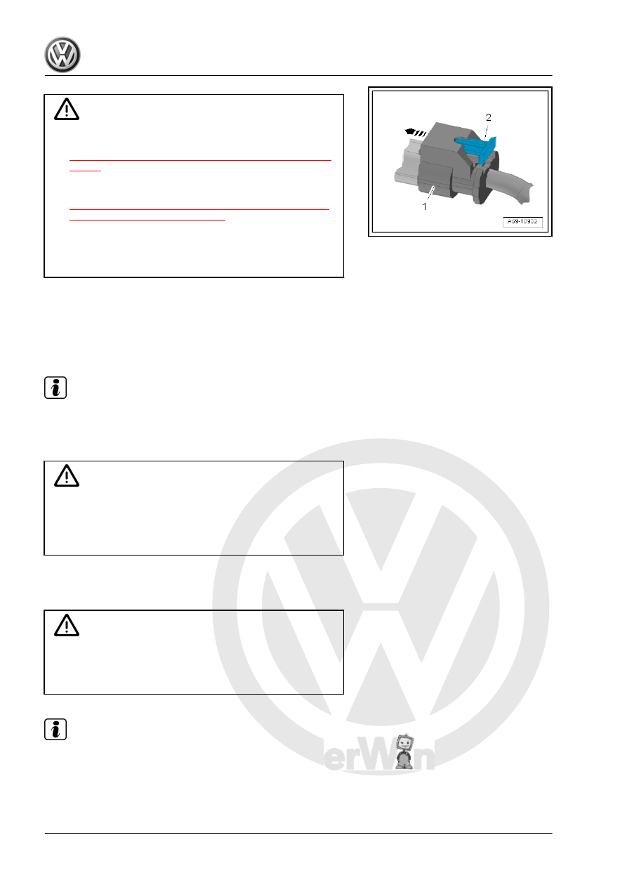
– Connect the connector -1- to the crash sensor until it clicks into
place -arrow-.
– Push in the connector lock -2- to secure the connector.
Installation is performed in reverse order of removal, while noting
the following:
Note
♦
Make sure the connectors are pushed in all the way and that
they engage audibly.
♦
Make sure the wires are not pinched.
WARNING
The ignition must be on when connecting the battery. If pyro‐
technic components (for example, airbag, belt tensioner) are
not repaired correctly, they may deploy unintentionally after
connecting battery. There must not be anyone inside the ve‐
hicle when connecting the battery.
– Connect the battery ground cable with the ignition turned on.
Refer to ⇒ Electrical Equipment; Rep. Gr. 27 ; Battery; Bat‐
tery, Disconnecting and Connecting .
WARNING
If the ignition is not switched on after the battery is reconnected
- “indicator lamps in the instrument cluster do not light up” - the
ignition (key/button) may only be switched on when the driver
seat is positioned all the way back.
Note
If the Airbag Indicator Lamp - K75- indicates a fault, check the
DTC memory, erase it and check it again using the Vehicle Di‐
agnostic Tester .