Volkswagen Golf / Golf GTI / Golf Variant. Service manual - part 378
10
Airbag Crash Sensors
⇒ “10.1 Component Location Overview - Airbag Crash Sensors”,
page 160
⇒ “10.2 Driver Front Airbag Crash Sensor G283 , Removing and
Installing”, page 161
⇒ “10.3 Passenger Side Front Airbag Crash Sensor G284 , Re‐
moving and Installing”, page 164
⇒ “10.4 Driver Side Airbag Crash Sensor G179 / Front Passenger
Side Airbag Crash Sensor G180 , Removing and Installing”, page
166
⇒ “10.5 Driver Side Rear Side Airbag Crash Sensor G256 / Pas‐
senger Side Rear Side Airbag Crash Sensor G257 , Removing
10.1
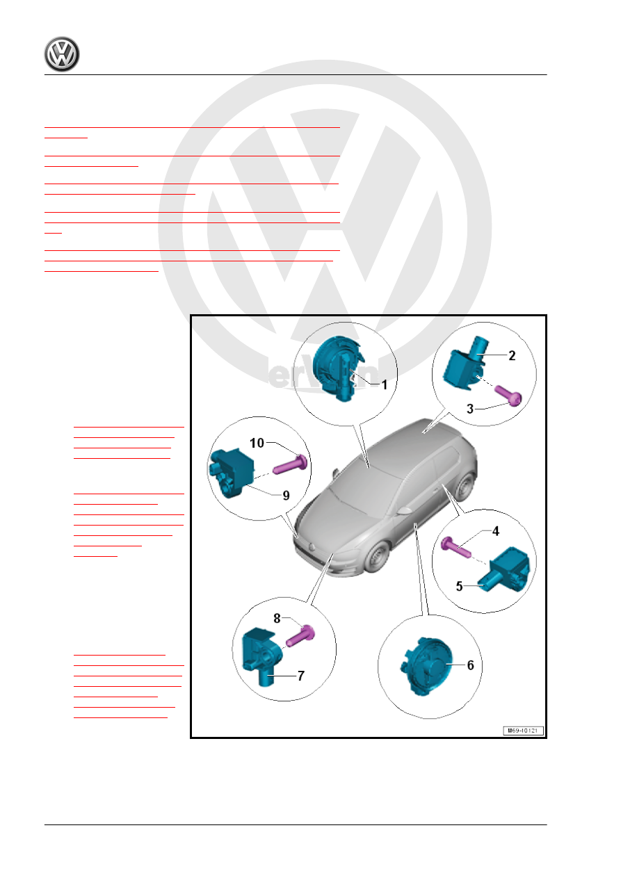
Component Location Overview - Airbag Crash Sensors
1 - Front Passenger Side Air‐
bag Crash Sensor - G180-
❑ Component location: in‐
side the door
❑ For the safety precau‐
tions for working with
front side airbag crash
sensors (pressure sen‐
sors). Refer to
❑ Removing and instal‐
ling. Refer to
2 - Passenger Side Rear Side
Airbag Crash Sensor - G257-
❑ Component location:
under the wheel hous‐
ing trim panel
❑ Removing and instal‐
ling. Refer to
.
3 - Screw
❑ 9 Nm
4 - Screw
❑ 9 Nm