Volkswagen Golf / Golf GTI / Golf Variant. Service manual - part 9


  Index      Volkswagen     Volkswagen Golf / Golf GTI / Golf Variant - service and repair manual 2013 year


Search            copyright infringement  


Content   ..  7  8  9  10   ..


Volkswagen Golf / Golf GTI / Golf Variant. Service manual - part 9


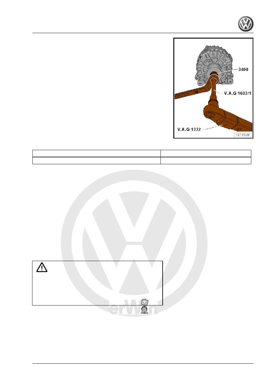
– Install the -VAG1603A/1- in the generator shaft.
– Counterhold the -3400- with a wrench (SW 17).
– Tighten the ribbed belt pulley by turning the generator shaft to

the left using -VAG1332- .

Tightening Specifications

Component

Tightening specification

Ribbed belt pulley nut

80 Nm

2.4.4

Decoupling Belt Pulley with Freewheel,

Removing and Installing

Special tools and workshop equipment required
♦ Adapter - T10474-
♦ Multi-Tooth Adapter - 3400-
♦ Torque Wrench 1332 40-200Nm - VAG1332-
♦ Torx Key Socket Set - VAG1603A/1-
General Information
There are different decoupling belt pulley with freewheel.
Before removing check which special tool must be used for the

removal of the decoupling belt pulley with freewheel.

Caution

The length of the ribbed belt is different depending on the de‐

coupling belt pulley with freewheel installed.
Check which decoupling belt pulley with freewheel is installed

and make sure that the correct ribbed belt will be installed.

Ribbed belt allocation. Refer to the Parts Catalog.

Decoupler Differences
-A- small decoupling belt pulley with freewheel, special tool to be

used -T10474-

-B- large decoupling belt pulley with freewheel, special tool to be

used -3400-

Note

The ribbed belt for the large decoupling belt pulley with freewheel

must be longer, because the decoupling belt pulley with freewheel

has a larger diameter and it is different for vehicles with and with‐

out an A/C system.

Removing
– Remove the Generator - C- . Refer to

⇒ “2.2 Generator, Removing and Installing”, page 15

 .

– Secure the Generator - C- in a vise by the mounting points.
– If equipped, remove the protective cap from the decoupling

belt pulley with freewheel.

– Install the -T10474- or -3400- -1- in the belt pulley and attach

a wrench (SW 17).

– Install the -VAG1603A/1- -2- in the generator shaft.
– Turn the generator shaft clockwise to loosen and while doing

so counterhold with the wrench.

– Hold the decoupling belt pulley with freewheel in place by hand

and turn it at the generator shaft until the decoupling belt pulley

with freewheel can be removed.

Installing
Install in reverse order of removal. Note the following:
The -VAG1332- must be rearranged for installing the decoupling

belt pulley with freewheel as follows:

– Release the insert -1- and remove it from the handle part -2-.
– Turn the handle part -2- of the torque wrench 180° and reinsert

the socket.

– Set the rotation direction of the torque wrench socket to “left”.
– Next, screw the ribbed belt pulley with freewheel by hand onto

the generator shaft until stop.

– Insert the -T10474- or the -3400- -1- into the decoupling belt

pulley with freewheel and attach a wrench.

– Install the -VAG1603A/1- -2- in the generator shaft.
– Turn the generator shaft using the -VAG1332- -3- counter

clockwise to tighten the decoupling belt pulley with freewheel.

Tightening Specifications

Component

Tightening Specification

Decoupling belt pulley nut

80 Nm

2.5

Voltage Regulator, Removing and In‐

stalling

⇒ “2.5.1 Voltage Regulator, Removing and Installing, Bosch”,

page 27
⇒ “2.5.2 Voltage Regulator, Removing and Installing, Valeo”,

page 28

2.5.1

Voltage Regulator, Removing and In‐

stalling, Bosch

Special tools and workshop equipment required
♦ Angled Screwdriver - VAS6416-
♦ Torque Screwdriver - VAG1624-
Removing
– Remove the Generator - C- . Refer to

⇒ “2.2 Generator, Removing and Installing”, page 15

 .

– Carefully pry out the cap -1- from the retainers in direction of

-arrows- using the -VAS6416- .

– Remove the screws -arrows- for the Voltage Regulator - C1- .

– Remove the Voltage Regulator - C1- from the Generator - C- .
Installing
Install in the reverse order of removal while paying attention to

the following:

Tightening Specifications

Component

Tightening Specification

Voltage Regulator - C1- screws

2 Nm

2.5.2

Voltage Regulator, Removing and In‐

stalling, Valeo

Special tools and workshop equipment required
♦ Torque Wrench 1783 - 2-10Nm - VAG1783-
Removing
– Remove the Generator - C- . Refer to

⇒ “2.2 Generator, Removing and Installing”, page 15

 .

– Carefully pry the cap -1- off of the Generator - C- .

– Remove the screws -2- for the Voltage Regulator - C1- -3-.
– Remove the Voltage Regulator - C1- -3- from the Generator -

C- .

Installing
Install in the reverse order of removal while paying attention to

the following:
– Install the Voltage Regulator - C1- .


Content   ..  7  8  9  10   ..