Volkswagen Golf Variant / Jetta. Manual - part 711
 

  Index      Volkswagen     Volkswagen Golf Variant (2007), Jetta (2005) - service repair manual


Search            


Content   ..  709  710  711  712   ..


Volkswagen Golf Variant / Jetta. Manual - part 711


ing:
– Tighten all threaded connections to specified torques

⇒ page 313

 .

Note

Tail light connector in side panel should engage „audibly“.

– When installation is complete, check gap/shut lines of tail light

to body.

9.11

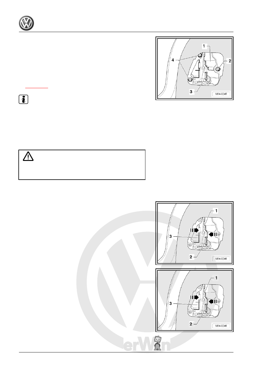
Removing and installing tail light bulb

holder - Variant

Caution

♦ Switch off ignition and all electrical consumers.
♦ Remove the ignition key.

Removing
– Push side panel trim/cover to the side.
– Disconnect connector -2-.

– Unclip fastening tabs -in direction of arrow- and unhook bulb

carrier -1- from tail light housing -3-.

Installing
Installation is carried out in reverse order of removal.

314

Removing and installing number

plate lights

Caution

♦ Switch off ignition and all electrical consumers.
♦ Remove the ignition key.

Removing
– Remove screws -arrows- from left number plate light -X4- .
– Remove lens with left number plate light -X4- .
Bulb: festoon C 12 V/5 W
Installing
Installation is carried out in reverse order of removal.

10. Removing and installing number plate lights    

315

Additional brake lights

11.1

Removing and installing additional

brake light bulb -M25- - saloon

Note

♦

Failure of LEDs in additional brake lights:

♦

The individual LEDs in the additional brake lights are com‐

prised in groups of four LEDs and are supplied with current in

groups.

♦

The additional brake light is designed in such a way that the

legal requirements are still met in the event that one LED group

fails.

♦

If a further LED group fails, these requirements are no longer

met according to the legislator.

♦

Due to the failure of one LED group, the intact LEDs are placed

under increased strain; it must be anticipated that further LED

groups will soon fail.

♦

If more than four individual LEDs in the additional brake light

have failed, the additional brake light must be renewed (repair

measure).

Caution

♦ Switch off ignition and all electrical consumers.
♦ Remove the ignition key.

Removing
– Remove strip roof leading edge ⇒  General body repairs, in‐

terior; Rep. gr.  70 .

– Disconnect connector -1-.
– Push high-level brake light bulb -M25- -in direction of arrow-

to rear window.

Installing
Carry out installation in the reverse sequence, noting the follow‐

ing:
– When installing additional brake light bulb -M25- , ensure the

seal is seated correctly.

11.2

Removing and installing additional

brake light bulb -M25- - estate

The additional brake light bulb -M25- is located in the roof spoiler

over the rear window.
The illumination of high-level brake light bulb -M25- is provided

by LEDs.
The additional brake light bulb -M25- cannot be dismantled.

316

-M25- must be renewed.
Special tools and workshop equipment required
♦ Removal wedge -T10039/1-

Caution

♦ Switch off ignition and all electrical consumers.
♦ Remove the ignition key.
♦ When removing and installing components that are in view

(switches, covers, trim), mask off areas where tools ( re‐

moval wedge -T10039/1- , removal wedge -VAS 3409- ,

screwdriver) are used to lever out those components us‐

ing commercially available masking tape.

♦ Ensure the seal is not damaged when removing the addi‐

tional brake light bulb -M25- .

Removing
– Insert removal wedge -T10039/1- between upper edge of

high-level brake light bulb -M25- and roof spoiler.

– Press additional brake light bulb -M25- downwards using re‐

moval wedge -T10039/1- and unclip upper retaining lugs of

additional brake light bulb -M25- towards rear.

– Then pull the additional brake light bulb -M25- to rear out of

opening in the roof spoiler, as far as the connected wiring al‐

lows.

11. Additional brake lights    

317


Content   ..  709  710  711  712   ..