Toyota Corolla (2004+). Manual - part 82
05-586
DIAGNOSTICS
- SUPPLEMENTAL RESTRAINT SYSTEM (April, 2003)
INSPECTION PROCEDURE
1
CHECK CONNECTOR
(a) Disconnect the negative (-) terminal cable from the battery, and wait at least for 90 seconds.
(b) Check the connection of the combination meter connector and the airbag sensor assy center connec-
tors.
OK:
The connectors are connected.
NG CONNECT CONNECTORS
OK
2
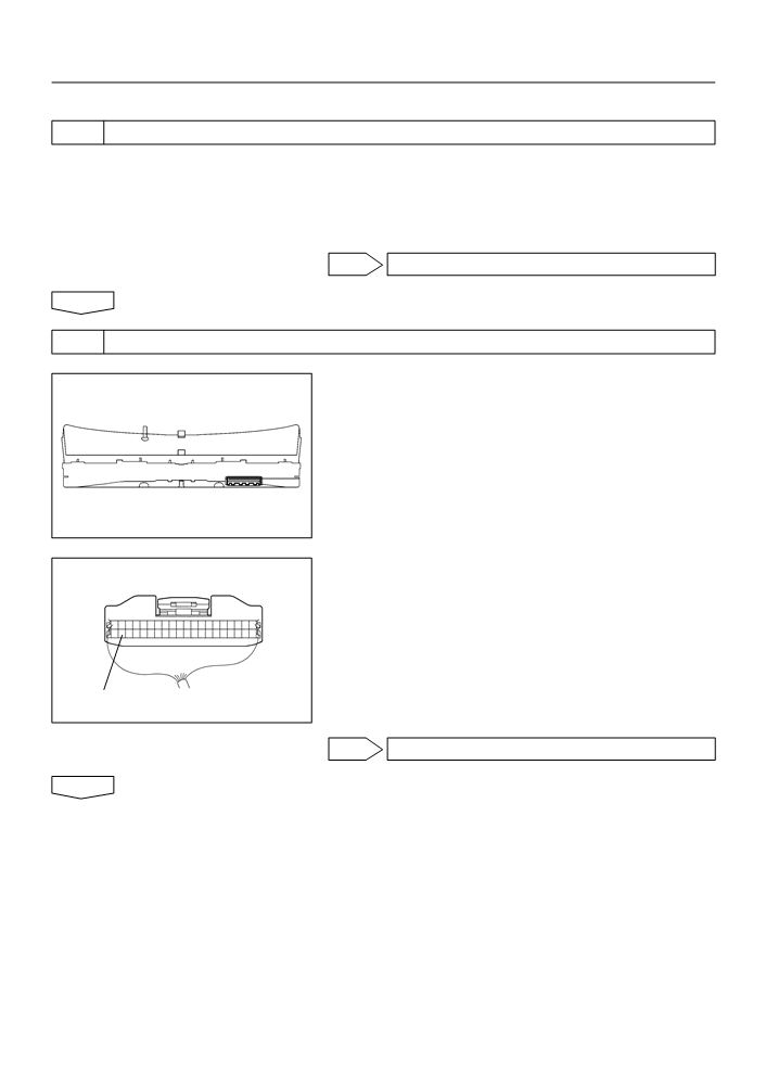
CHECK COMBINATION METER ASSY
(a) Disconnect the connector from the combination meter.
(b) Connect the negative (-) terminal cable to the battery,
and wait at least for 2 seconds.
H42000
(c)
Turn the ignition switch to ON, and wait at least for 6 se-
conds.
(d) Measure the voltage between SW and body ground.
OK:
Voltage: Above 8 V
SW
H41993
NG REPLACE COMBINATION METER ASSY
OK

05-587
DIAGNOSTICS
- SUPPLEMENTAL RESTRAINT SYSTEM (April, 2003)
3
CHECK INSTRUMENT PANEL WIRE(AIRBAG SENSOR ASSY
CENTER-COMBINATION METER ASSY)
(a) Turn the ignition switch to LOCK.
(b) Disconnect the negative (-) terminal cable from the bat-
tery, and wait at least for 90 seconds.
(c)
Disconnect the connector from the airbag sensor assy
LA
center.
(d) Measure the resistance between LA and body ground.
OK:
Resistance: 1M W or Higher
H40065
NG REPAIR OR REPLACE INSTRUMENT PANEL
WIRE (AIRBAG SENSOR ASSY CENTER - COM-
BINATION METER ASSY)
OK
REPLACE AIR BAG SENSOR ASSY CENTER
4
CHECK INSTRUMENT PANEL WIRE(AIRBAG SENSOR ASSY
CENTER-COMBINATION METER ASSY)
(a) For the connector (on the airbag sensor assy center side)
Airbag Sensor Assy Center:
between the combination meter and the airbag sensor
assy center, measure the resistance between SW and
LA.
OK:
Resistance: Below 1
W
LA
Combination Meter:
SW
H41994
NG REPAIR OR REPLACE INSTRUMENT PANEL
WIRE (AIRBAG SENSOR ASSY CENTER - COM-
BINATION METER ASSY)
OK
REPLACE AIR BAG SENSOR ASSY CENTER

05-436
DIAGNOSTICS
- SUPPLEMENTAL RESTRAINT SYSTEM (April, 2003)
0525C-13
PROBLEM SYMPTOMS TABLE
HINT:
Proceed with troubleshooting of each circuit in the table below.
Symptom
Suspect Area
See page
F When the ignition switch is in the ON position, the SRS warning
light sometimes comes on after approximately 6 seconds.
F SRS warning light circuit malfunction
05-585
F SRS warning light always comes on even when DTC is not out-
(Always lights up, when DTC is not output).
put.
F With the ignition switch is in the ON position, the SRS warning
F SRS warning light circuit malfunction
05-588
light does not come on.
(Does not light up, when ignition switch is turned to ON).
F Although a SRS warning light operates normally, DTC or a nor-
mal system code is not displayed.
F TC terminal circuit
05-590
F Although the terminals TC and CG are not connected, DTC or a
normal system code are displayed.

05-590
DIAGNOSTICS
- SUPPLEMENTAL RESTRAINT SYSTEM (April, 2003)
055ZW-05
TC TERMINAL CIRCUIT
CIRCUIT DESCRIPTION
DTC output mode is set by connecting between TC and CG of the DLC3.
The DTCs are displayed by blinking the SRS warning light.
WIRING DIAGRAM
D1
Airbag Sensor Assy Center
DLC3
Center J/B
Instrument Panel J/B
3
5
4
1
19
P-B
P-B
Tc
4C
4C P-B
IJ
II
A13 Tc
13
16
21
W-B
W-B
CG
4B
4B
4
A
J6
JC
IE
H42006
HINT:
When each warning light stays blinking, ground short in the wiring until the terminal TC of the DLC3 or internal
ground short in each ECU is suspected.

05-591
DIAGNOSTICS
- SUPPLEMENTAL RESTRAINT SYSTEM (April, 2003)
INSPECTION PROCEDURE
1
CHECK WIRE HARNESS(DLC3 - AIRBAG SENSOR ASSY CENTER)
(a) Turn the ignition switch to the LOCK position.
DLC3:
TC
(b) Disconnect the aribag sensor assy center connector.
(c)
Measure the resistance according to the value(s) in the
table below.
Standard:
Tester connection
Condition
Specified condition
TC - TC
Always
Below 1 W
Airbag Sensor Assy Center:
TC
NG REPAIR OR REPLACE WIRE HARNESS(TC of
ELC3 - TC of AIRBAG SENSOR ASSY CENTER)
H40173
H40065
H43360
OK
2
CHECK WIRE HARNESS(CG of DLC3 - BODY GROUND)
(a) Measure the resistance according to the value(s) in the
table below.
Standard:
Tester connection
Condition
Specified condition
CG - Body ground
Always
Below 1 W
CG
H40173
NG REPAIR OR REPLACE WIRE HARNESS(CG of
DLC3 - BODY GROUND)
OK

05-592
DIAGNOSTICS
- SUPPLEMENTAL RESTRAINT SYSTEM (April, 2003)
3
CHECK WIRE HARNESS(TC of AIRBAG SENSOR ASSY CENTER - BODY
GROUND)
(a) Measure the resistance according to the value(s) in the
table below.
Standard:
Tester connection
Condition
Specified condition
TC - Body ground
Always
1 MW or Higher
TC
H40065
NG REPAIR OR REPLACE WIRE HARNESS AND
EACH ECU
OK
REPLACE AIR BAG SENSOR ASSY CENTER
05-434
DIAGNOSTICS
- SUPPLEMENTAL RESTRAINT SYSTEM (April, 2003)
05DQA-01
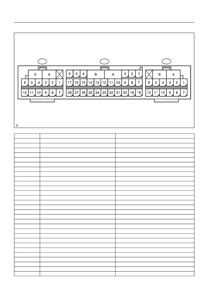
TERMINALS OF ECU
A12
A13
A14
H40028
No.
Symbol
Terminal Name
A
-
Electrical Connector Check Mechanism
B
-
Electrical Connector Check Mechanism
A13-3
LA
SRS Warning Light
A13-5
IG2
Power Source (IG2 Fuse)
A13-7
P2-
Squib (Passenger (2 step))
A13-8
P2+
Squib (Passenger (2 step))
A13-9
+SR
Front Airbag Sensor (RH)
A13-10
P+
Squib (Passenger)
A13-11
P-
Squib (Passenger)
A13-12
SIL
Diagnosis
A13-13
D-
Squib (Driver)
A13-14
D+
Squib (Driver)
A13-15
+SL
Airbag Front Sensor (LH)
A13-16
D2+
Squib (Driver (2 step))
A13-17
D2-
Squib (Driver (2 step))
A13-19
Tc
Diagnosis
A13-20
-SR
Airbag Front Sensor (RH)
A13-23
GSW2
ECM
A13-26
-SL
AIrbag Front Sensor (LH)
A13-27
E1
Ground
A13-28
E2
Ground
A12-1
PL-
Squib (Seat Belt Pretensioner, LH)
A12-2
PL+
Squib (Seat Belt Pretensioner, LH)
A12-3
LSP+
Seat Position Sensor
A12-4
LSP-
Seat Position Sensor
A12-5
SFL-
Squib (Side, LH)
A12-6
SFL+
Squib (Side, LH)
A12-7
VUPL
Side Airbag Sensor Assy (LH)
A12-9
SSL-
Side Airbag Sensor Assy (LH)

05-435
DIAGNOSTICS
-
SUPPLEMENTAL RESTRAINT SYSTEM (April, 2003)
No.
Symbol
Terminal Name
A12-10
FSL
Side Airbag Sensor Assy (LH)
A12-11
LBE+
Seat Belt Buckle Switch (LH)
A12-12
ESL
Side Airbag Sensor Assy (LH)
A14-1
SFR+
Squib (Side, RH)
A14-2
SFR-
Squib (Side, RH)
A14-5
PR+
Squib (Seat Belt Pretensioner, RH)
A14-6
PR-
Squib (Seat Belt Pretensioner, RH)
A14-7
ESR
Side Airbag Sensor Assy (RH)
A14-9
FSR
Side Airbag Sensor Assy (RH)
A14-10
SSR-
Side Airbag Sensor Assy (RH)
A14-12
VUPR
Side Airbag Sensor Assy (RH)

05-421
DIAGNOSTICS
- SUPPLEMENTAL RESTRAINT SYSTEM (April, 2003)
SUPPLEMENTAL RESTRAINT SYSTEM (Apr., 2003)
05256-15
HOW TO PROCEED WITH TROUBLESHOOTING
The hand-held tester can be used at step 4, 6, 8 and 9.
1
VEHICLE BROUGHT TO WORKSHOP
2
CUSTOMER PROBLEM ANALYSIS (See page 05-423)
3
WARNING LIGHT CHECK (See page 05-424)
4
THE DTCs CHECK (Present and Past DTCs) (See page
05-424)
DTCs IS OUTPUT (INCLUDING NORMAL SYS-
TEM CODE): Go to step 5
DTCs IS NOT OUTPUT: PROBLEM SYMPTOMS
TABLE (See page 05-436)
5
THE DTCs CHART (See page 05-430)
6
CIRCUIT INSPECTION (See page 05-437 to 05-579)
TROUBLE CODE IS OUTPUT: Go to step 7
NORMAL SYSTEM CODE IS OUTPUT: Go to step
11
7
REPAIR
8
CLEAR THE DTCs (Present and Past DTCs) (See page
05-424)

05-422
DIAGNOSTICS
- SUPPLEMENTAL RESTRAINT SYSTEM (April, 2003)
9
THE DTCs CHECK (Present and Past DTCs) (See page
05-424)
DTCs IS NOT OUTPUT: Go to step 10
DTCs IS OUTPUT: Go to step 5
10
SYMPTOM SIMULATION (See page 01-20)
WARNING LIGHT REMAINS OFF: Go to step 11
WARNING LIGHT IS ON: Go to step 5
11
CONFIRMATION TEST
END

DIAGNOSTICS
- TOYOTA VEHICLE INTRUSION PROTECTION
05-701
SYSTEM
057RU-01
CUSTOMER PROBLEM ANALYSIS CHECK
TVIP SYSTEM Check Sheet
Inspector’s name:
Registration No.
Customer’s Name
Registration Year
Frame No.
Date Vehicle
km
/
/
Odometer Reading
Brought in
Mile
Date Problem First Occurred
/
/
F Constant F Sometimes ( Times per day, month)
Frequency Problem Occurs
F Once only
F Fine
F Cloudy
F Rainy
F Snowy
Weather
Weather Conditions
F Various/Others
When Problem
F Hot F Warm
F Cool
Occurred
Outdoor temperature
F Cold (Approx.
F (
C))
Problem Symptom
F TVIP system cannot be set.
F Indicator light does not flash when the TVIP system is set.
(It stays on or does not light at all.)
F TVIP system
F When unlocked using the
Malfunction
does not operate.
front door lock knob.
F Horn only
F When the doors or
F Headlights only
luggage is opened.
F Hazard lights only
F Room light only
F Forced door lock operation only
F System cannot be
F When door is unlocked using key or wireless door lock control system.
canceled, once set.
F When the key is inserted in the ignition key cylinder and turned to ACC or ON
position.
(However, only when the system has never operated)
F System cannot be
F When door is unlocked using key or wireless door lock control system.
canceled during warning
F When the key is inserted in the ignition key cylinder and turned to ON
operation.
position.
F Warning operation starts when the system is set and the door is opened with the key.
F Others.

DIAGNOSTICS
- TOYOTA VEHICLE INTRUSION PROTECTION
05-733
SYSTEM
057S7-01
DOOR COURTESY SWITCH CIRCUIT
CIRCUIT DESCRIPTION
The door courtesy switch turns ON when the door is opened and OFF when the door is closed.
WIRING DIAGRAM
I11
Integration Relay
TVIP ECU
9
R-W
T3
DMLP
R-W
PCTY
13
D5
R-W
LP
Door Courtesy SW
3
Instrument Panel J/B
Front RH
R-W
1
4
19
R
PRCTY
IK
T3
CTY
6
3
40
R-W
DCTY
IL
T3
DSWD
5
D4
Door Courtesy SW Front LH
1
R-W
ID
1
L4
Luggage Compartment
J10
Light SW
J/C
35
R-W
R-W 11
R-W
ID2
T3
DSWL
1
A
A
D7
Door Courtesy SW
Rear RH
15
R-Y
ID
1
D6
Door Courtesy SW Rear LH
14
R-B
ID
1
898

05-734
DIAGNOSTICS
- TOYOTA VEHICLE INTRUSION PROTECTION
SYSTEM
INSPECTION PROCEDURE
1
CHECK COURTESY LAMP SWITCH
(a) Check the courtesy switch, as shown in the illustration
and table.
Free
Standard:
Terminal No.
Switch position
Specified condition
Push
Continuity
1 Body ground
Free
No continuity
Push
NG REPLACE COURTESY LAMP SWITCH
B59818
OK
2
CHECK WIRE HARNESS (INTEGRATION RELAY DOOR COURTESY SW)
(a) Disconnect the integration relay and door courtesy con-
Integration Relay
nectors.
(Wire Harness Side)
(b) Check the continuity between the terminals of the integra-
I11
tion relay and door courtesy switch connectors, as shown
in the illustration and table.
Standard:
Terminal No.
Specified condition
(Integration relay Door courtesy SW)
I11-13 D5-1
Continuity
D5
Door Courtesy SW Front RH
(Wire Harness Side)
B60033
B59191
B59599

DIAGNOSTICS
- TOYOTA VEHICLE INTRUSION PROTECTION
05-735
SYSTEM
(c)
Disconnect the each door courtesy switch connectors.
Integration Relay (Instrument Panel J/B)
(d) Check the continuity between the terminals of the integra-
(Wire Harness Side)
tion relay and door courtesy switch connectors, as shown
ID
in the illustration and table.
Standard:
Terminal No.
Specified condition
(Integration relay Door courtesy SW)
ID-1 D4-1
ID-15 D7-1
Continuity
D4
ID-14 D6-1
Door Courtesy SW Front LH
D7
Door Courtesy SW Rear RH
D6
Door Courtesy SW Rear LH
(Wire Harness Side)
NG REPAIR OR REPLACE WIRE HARNESS AND
CONNECTOR
B59527
B59191
B59598
OK
3
CHECK WIRE HARNESS (TVIP ECU LUGGAGE COMPARTMENT LIGHT SW)
(a) Disconnect the TVIP ECU and luggage comportment
TVIP ECU
light switch connectors.
(Wire Harness Side)
(b) Check the continuity between the terminals of the TVIP
ECU and luggage compartment light switch connectors,
as shown in the illustration and table.
Standard:
T3
Symbols (Terminal No.)
Specified condition
(TVIP ECU Luggage compartment light SW)
DSWL (T3-35) L4-1
Continuity
DSWL (35)
Luggage Compartment Light SW
(Wire Harness Side)
L4
NG REPAIR OR REPLACE WIRE HARNESS AND
B52239
CONNECTOR
B59191
B59597
OK
PROCEED TO NEXT CIRCUIT INSPECTION SHOWN ON PROBLEM SYMPTOMS TABLE
(See page 01-30)

05-738
DIAGNOSTICS
- TOYOTA VEHICLE INTRUSION PROTECTION
SYSTEM
057S9-01
DOOR KEY LOCK AND UNLOCK SWITCH CIRCUIT
CIRCUIT DESCRIPTION
The door key lock and unlock switch is built in the door lock motor.
WIRING DIAGRAM
D8
TVIP ECU
Door Key Lock and Unlock SW Front LH
Door Lock Motor Front LH
Door Unlock Detection SW Front LH
Unlock
10
17
L-Y
L-Y
IC1
T3
UL3
10
6
W-B
W-B
IC1
7
11
16
G
G
G
IC1
T3
L2
9
Lock
G
Center J/B
2
1
D9
G
4A
4A
Door Key Lock and Unlock SW Front RH
Door Lock Motor Front RH
Door Unlock Detection SW Front RH
Lock
11
G
G
IJ2
6
1
W-B
IJ2
8
10
18
L-B
L-B
IJ2
T3
UL2
5
Unlock
W-B
A
A
J6
J7
J/C
J/C
IE
IG
I24325
B59186