Toyota Corolla (2004+). Manual - part 81

05-431
DIAGNOSTICS
-
SUPPLEMENTAL RESTRAINT SYSTEM (April, 2003)
F SHORT IN P/T SQUIB (RH) CIRCUIT
F Seat belt pretensioner RH (squib)
B0130/63
F Airbag sensor assy center
Blink
(05-494)
F Instrument panel wire No.3
F OPEN IN P/T SQUIB (RH) CIRCUIT
F Seat belt pretensioner RH (squib)
B0131/64
F Airbag sensor assy center
Blink
(05-498)
F Instrument panel wire No.3
F SHORT IN P/T SQUIB (RH) CIRCUIT
F Seat belt pretensioner RH (squib)
B0132/61
(TO GROUND)
F Airbag sensor assy center
Blink
(05-501)
F Instrument panel wire No.3
F SHORT IN P/T SQUIB (RH) CIRCUIT
F Seat belt pretensioner RH (squib)
B0133/62
(TO B+)
F Airbag sensor assy center
Blink
(05-504)
F Instrument panel wire No.3
F SHORT IN P/T SQUIB (LH) CIRCUIT
F Seat belt pretensioner LH (squib)
B0135/73
F Airbag sensor assy center
Blink
(05-507)
F Instrument panel wire No.3
F OPEN IN P/T SQUIB (LH) CIRCUIT
F Seat belt pretensioner LH (squib)
B0136/74
F Airbag sensor assy center
Blink
(05-511)
F Instrument panel wire No.3
F SHORT IN P/T SQUIB (LH) CIRCUIT
F Seat belt pretensioner LH (squib)
B0137/71
(TO GROUND)
F Airbag sensor assy center
Blink
(05-514)
F Instrument panel wire No.3
F SHORT IN P/T SQUIB (LH) CIRCUIT
F Seat belt pretensioner LH (squib)
B0138/72
(TO B+)
F Airbag sensor assy center
Blink
(05-517)
F Instrument panel wire No.3
B1100/31
F AIRBAG SENSOR ASSY CENTER
F Airbag sensor assy center
ON
(05-520)
MALFUNCTION
B1135/24
F HALF CONNECTION DETECTION
F Airbag sensor assy center
ON
(05-522)
MALFUNCTION
F SIDE AIRBAG SENSOR ASSY (RH)
F Airbag sensor assy center
B1140/32
MALFUNCTION
F Side Airbag sensor assy RH
Blink
(05-524)
F Instrument panel wire No.3
F SIDE AIRBAG SENSOR ASSY (LH)
F Airbag sensor assy center
B1141/33
MALFUNCTION
F Side Airbag sensor assy LH
Blink
(05-529)
F Instrument panel wire No.3
F SEAT POSITION AIRBAG SENSOR
F Seat position airbag sensor
ASSY MALFUNCTION
F Airbag sensor assy center
B1153/25
F Instrument panel wire No.3
ON
(05-534)
F Wire harness (Seat position airbag sensor - Front seat inner
belt assy)
F FRONT AIRBAG SENSOR (RH)
F Airbag front RH sensor
B1156/B1157
MALFUNCTION
F Airbag sensor assy center
/15
ON
F Engine room main Instrument panel wire No.3
(05-542)
F Instrument panel wire
F FRONT AIRBAG SENSOR (LH)
F Airbag sensor front LH
B1158/B1159
MALFUNCTION
F Airbag sensor assy center
/16
ON
F Engine room main Instrument panel wire No.3
(05-548)
F Instrument panel wire
F SHORT IN D SQUIB (2ND STEP)
F Horn button assy (D squib (2nd step))
B1180/17
CIRCUIT
F Spiral cable sub-assy
ON
(05-554)
F Airbag sensor assy center
F Instrument panel wire No.3
F OPEN IN D SQUIB (2ND STEP)
F Horn button assy (D squib (2nd step))
B1181/18
CIRCUIT
F Spiral cable sub-assy
ON
(05-558)
F Airbag sensor assy center
F Instrument panel wire No.3
F SHORT IN D SQUIB (2ND STEP)
F Horn button assy (D squib (2nd step))
B1182/19
CIRCUIT (TO GROUND)
F Spiral cable sub-assy
ON
(05-562)
F Airbag sensor assy center
F Instrument panel wire No.3

05-432
DIAGNOSTICS
- SUPPLEMENTAL RESTRAINT SYSTEM (April, 2003)
F SHORT IN D SQUIB (2ND STEP)
F Horn button assy (D squib (2nd step))
B1183/22
CIRCUIT (TO B+)
F Spiral cable sub-assy
ON
(05-566)
F Airbag sensor assy center
F Instrument panel wire No.3
F SHORT IN P SQUIB (2ND STEP)
F Instrument panel passenger airbag assy (P squib (2nd step))
B1185/57
CIRCUIT
F Airbag sensor assy center
ON
(05-570)
F Instrument panel wire
F OPEN IN P SQUIB (2ND STEP)
F Instrument panel passenger airbag assy (P squib (2nd step))
B1186/58
CIRCUIT
F Airbag sensor assy center
ON
(05-573)
F Instrument panel wire
F SHORT IN P SQUIB (2ND STEP)
F Instrument panel passenger airbag assy (P squib (2nd step))
B1187/55
CIRCUIT (TO GROUND)
F Airbag sensor assy center
ON
(05-576)
F Instrument panel wire
F SHORT IN P SQUIB (2ND STEP)
F Instrument panel passenger airbag assy (P squib (2nd step))
B1188/56
CIRCUIT (TO B+)
F Airbag sensor assy center
ON
(05-579)
F Instrument panel wire
F SYSTEM NORMAL
-
OFF
Normal
F VOLTAGE SOURCE DROP
F Battery
(05-582)
ON
F Airbag sensor assy center
HINT:
F
When the SRS warning light remains lit up and the DTC is the normal code, this means a voltage source
drops.
This malfunction is not stored in memory by the Airbag sensor assy center and if the power source
voltage returns to normal, the SRS warning light will automatically go out.
F
When 2 or more codes are indicated, the codes will be displayed in numeral order starting from the
lowest numbered code.
F
If a code not listed on the chart is displayed, the Airbag sensor assy center is faulty.
F
In the case of any malfunction concerning any open circuit, ground short, or B+ short due to any squib,
another malfunction code may not be detected. In this case, correct the malfunction currently being
output, and then perform malfunction diagnosis again. Another malfunction code may then be de-
tected.
05-433
DIAGNOSTICS
- SUPPLEMENTAL RESTRAINT SYSTEM (April, 2003)
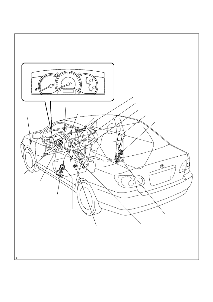
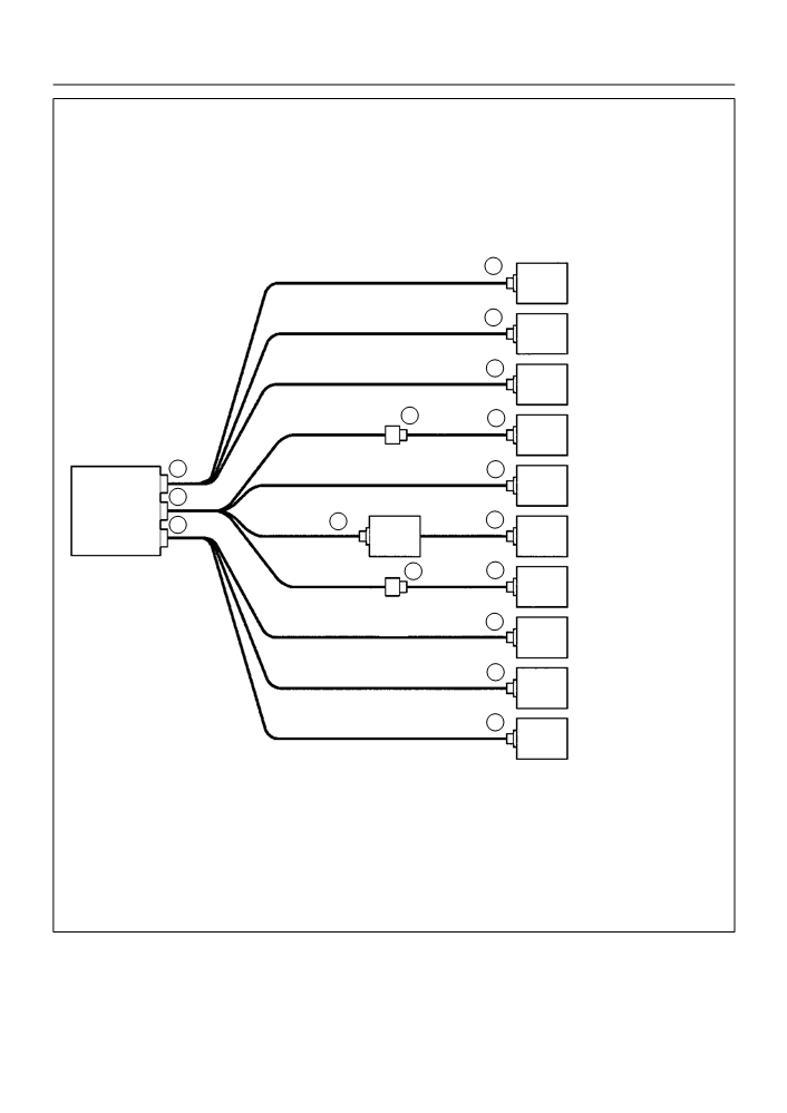
0525A-13
LOCATION
Combination Meter (Warning Light)
Instrument Panel Passenger Airbag Assy
Front Seat Airbag Assy LH
Horn Button Assy (w/ Airbag)
Airbag Sensor Assy Center
Airbag Sensor
Airbag Front RH Sensor
Front Seat Airbag Assy RH
Front LH
Side Airbag Sensor Assy RH
DLC3
Spiral Cable Sub-Assy
Seat Belt Pretensioner LH
Side Airbag Sensor Assy LH
Seat Belt Pretensioner RH
Seat Belt Buckle Switch LH
Seat Position Airbag Sensor
H41998
05-424
DIAGNOSTICS
- SUPPLEMENTAL RESTRAINT SYSTEM (April, 2003)
05258-08
PRE-CHECK
1.
SRS WARNING LIGHT CHECK
(a) Turn the ignition switch to the ON position and check that
the SRS warning light lights up.
(b) Check that the SRS warning light goes out after approx.
6 seconds.
HINT:
F
When the ignition switch is at ON and the SRS warning
C93955
light remains on or flashes, the airbag sensor assembly
has detected a malfunction code.
F
If, after approx. 6 second have elapsed, the SRS warning
light sometimes lights up, a short in the SRS warning light
circuit can be considered likely. Proceed to ”SRS warning
light circuit malfunction” on page
05-585 and 05-588.
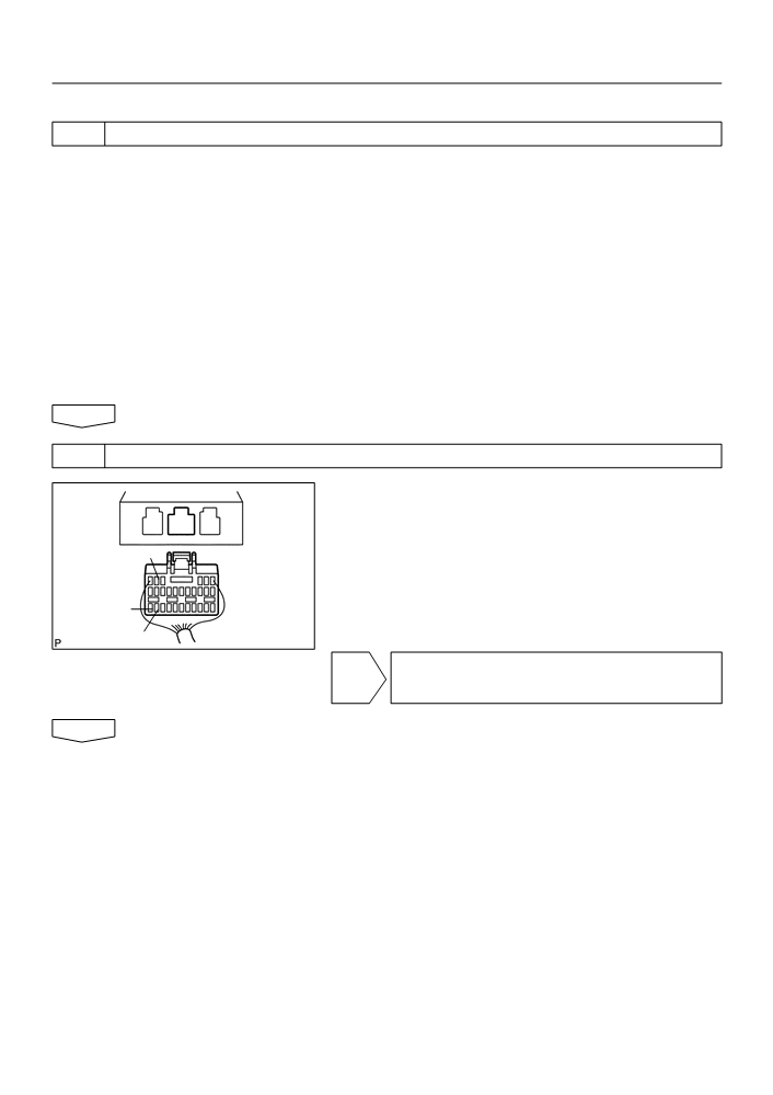
2.
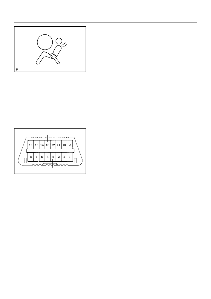
DTC CHECK ( using diagnosis check wire)
Tc
(a) Present troubles codes:
Output the DTC.
(1)
Turn the ignition switch to the ON position and wait
for approx. 60 seconds.
(2)
Using SST, connect terminals Tc and CG of the
DLC3.
SST
09843-18040
CG
H40173
NOTICE:
Pay due attention to the terminal connecting position to
avoid a malfunction.
(b) Past troubles codes:
Output the DTC.
(1)
Using service wire, connect terminals Tc and CG of
the DLC3.
SST
09843-18040
(2)
Turn the ignition switch to the ON position and wait
for approx. 60 seconds.
NOTICE:
Pay due attention to the terminal connecting position to
avoid a malfunction.
05-425
DIAGNOSTICS
- SUPPLEMENTAL RESTRAINT SYSTEM (April, 2003)
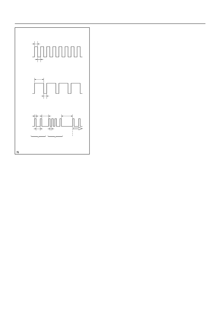
(c)
Read the DTC.
Normal Code (w/o Past Trouble Code)
Read the 2-digit DTC as indicated by the number of times
0.25
the SRS warning light blinks. As an example, the blinking
ON
patterns, normal, 11 and 31 are shown in the illustration.
F
Normal code indication (w/o past trouble
OFF
code)
The light will blink 2 times per second.
0.25
F
Normal code indication (w/ past trouble code)
Normal Code (w/ Past Trouble Code)
When the past troubles code is stored in the
0.75
airbag sensor assembly, the light blinks only
ON
ones a second.
F
Malfunction code indication
OFF
The first blinking output indicates the first digit
of a 2-digit DTC. After a 1.5-second pause,
0.25
Malfunctioning Code
the second blinking output will indicate the
(Example Code 11 and 31)
second digit.
0.5
2.5
4.0
If there are 2 or more codes, there will be a 2.5-second pause
between each code. After all the codes have been output, there
will be a 4.0-second pause and they will all be repeated.
HINT:
1.5
0.5
Repeat
In the event of a number of trouble codes, indication will start
DTC11
DTC31
from the smallest numbered code.
H13050
3.
DTC CHECK (Using hand-held tester)
(a) Hook up the hand-held tester to the DLC3.
(b) Read the DTCs by following the prompts on the tester screen.
HINT:
Please refer to the hand-held tester operator’s manual for further details.
4.
DTC CLEARANCE (Not using service wire)
(a) When the ignition switch is turned off, the diagnostic trouble code is cleared.
HINT:
DTC might not be cleared by turning the ignition switch OFF. In this case, proceed to the next step.
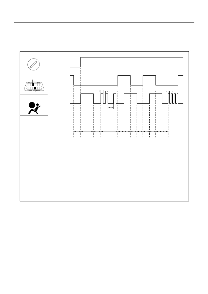
5.
DTC CLEARANCE (Using service wire)
(a) Using a service wire, connect terminals TC and CG of the DLC3.
(b) Disconnect terminal TC of DLC3 within 10 seconds after the DTC begins to be output, and check if
the warning light lights up within 3 seconds.
(c)
Within 2.0 seconds to 4.0 seconds after the SRS warning light lights up, connect the terminals TC and
CG of the DLC3.
(d) Light the SRS warning light goes off 2.0 to 4.0 seconds after connecting the terminals TC and CG of
DLC3, then disconnect the terminal TC of the DLC3 2.0 to 4.0 seconds after the warning light goes
off.
(e) Light the SRS warning light on again 3 seconds after disconnecting terminal TC of DLC3, then within
2.0 to 4.0 seconds after the lighting, connect terminals TC and CG of the DLC3.
(f)
Check if the SRS warning light goes off 2.0 to 4.0 seconds after connecting terminals TC and CG of
DLC3, and the correct code is output 1 second after the SRS warning goes off.
05-426
DIAGNOSTICS
- SUPPLEMENTAL RESTRAINT SYSTEM (April, 2003)
If DTCs are to cleared, repeat the above procedure until the codes are cleared.
IG S/W
ON
OFF
DLC3
Open
TC
Short
0.5 sec.
0.5 sec.
0.25 sec.
0.25 sec.
CG
SRS Warning
Light (*)
1.5 sec.
T1
T2
T3
T4
T5 T6
T5 T6 T5 T6 T5 T7
T1: 0 - second
T2: approx. 6 second
T3: 3 - 5 second
T4: 3 - 10 second
T5: 2 - 4 second
T6: 1 - 5 second
T7: within 1 second
*: The past trouble code in the illustration shows DTC 21 as an example.
H41917
05-427
DIAGNOSTICS
-
SUPPLEMENTAL RESTRAINT SYSTEM (April, 2003)
6.
DTC CLEARANCE (Using hand-held tester)
(a) Hook up the hand-held tester to the DLC3.
(b) Clear the DTCs by following the prompts on the tester screen.
HINT:
Please refer to the hand-held tester operation’s manual for further details.
7.
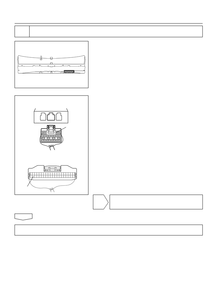
RELEASE METHOD OF AIRBAG ACTIVATION PREVENTION MECHANISM
(a) An airbag activention prevention mechanism is built into the connector for the squib circuit of the SRS.
When release of the airbag activation prevention mechanism is directed in the troubleshooting proce-
dure, as shown in the illustration of the connectors on the next pages, insert paper which has the same
thickness as the male terminal between the terminal and the short spring.
CAUTION:
Never release the airbag activation prevention mechanism on the squib connector.
NOTICE:
F
Do not release the airbag activation prevention mechanism unless specifically directed by the
troubleshooting procedure.
F
If the inserted paper is too thick the terminal and short spring may be damaged, so always use
paper with the same thickness as the male terminal.
05-428
DIAGNOSTICS
- SUPPLEMENTAL RESTRAINT SYSTEM (April, 2003)
7
Side Airbag
Sensor Assy (RH)
8
Front Seat Airbag
Assy (RH) (Squib)
9
Seat Belt
Pretensioner (RH)
10
11
Front Airbag Sensor (RH)
2
6
Instrument Panel
Passenger Airbag
Airbag
1
Spiral Cable Sub-Assy
Assy (Squib)
Sensor
4
5
Assy Center
3
Horn Button
Assy (Squib)
12
13
Front Airbag Sensor (LH)
14
Seat Belt
Pretensioner (LH)
15
Front Seat Airbag
Assy (LH) (Squib)
16
Side Airbag
Sensor Assy (LH)
H41916

05-429
DIAGNOSTICS
- SUPPLEMENTAL RESTRAINT SYSTEM (April, 2003)
Airbag Sensor Assy Center Connector
2
1
3
Short Spring Short Spring
Short Spring
Short Spring
After Release
Before Release
Paper
Connector
4
Before Release
After Release
Paper
Short Spring
Connector
6
Before Release
After Release
Paper
Short Spring
Connector
8
15
Before Release
After Release
Paper
Short Spring
H41995

05-582
DIAGNOSTICS
- SUPPLEMENTAL RESTRAINT SYSTEM (April, 2003)
055ZT-07
SOURCE VOLTAGE DROP
CIRCUIT DESCRIPTION
The SRS is equipped with a voltage-increase circuit (DC-DC converter) in the airbag sensor assy center
in case the source voltage drops.
When the battery voltage drops, the voltage-increase circuit (DC-DC converter) functions to increase the
voltage of the SRS to normal voltage.
The diagnosis system malfunction display for this circuit is different from other circuits that is when the SRS
warning light remains lit up and the DTC is a normal code, source voltage drop is indicated.
Malfunction in this circuit is not recorded in the airbag sensor assy center, and the source voltage returns
to normal, the SRS warning light automatically goes off.
DTC No.
Diagnosis
(Normal)
Source voltage drop
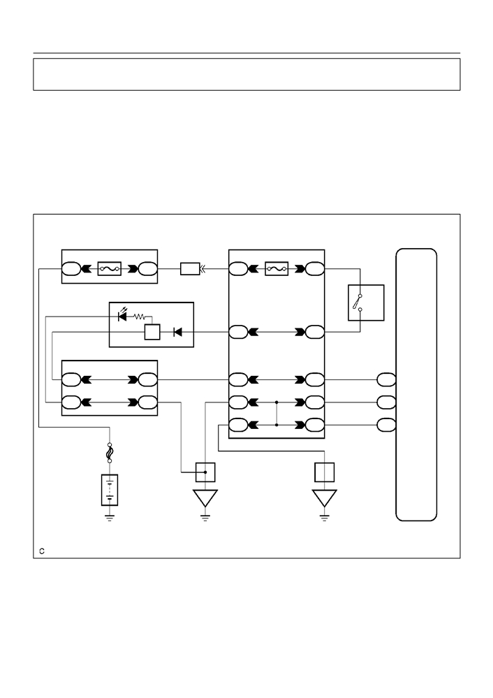
WIRING DIAGRAM
Engine Room R/B and J/B
Airbag Sensor Assy Center
1
MAIN
B
B-R
1A
1
1
2
I10
Instrument Panel J/B
Ignition SW
6
AM-2
3
2
B-W
B
B-R
IM
IM
IA4
6
5
IG2
AM2
5
5
8
B-W
B-O
IL
II
A13
IG2
4
3
27
W-B
W-B
IF
II
A13
E1
10
10
28
W-B
W-B
IH
II
A13
E2
W-B
FL MAIN
W-B
A
A
J6
J7
J/C
J/C
Battery
IE
IG
H42004
05-583
DIAGNOSTICS
- SUPPLEMENTAL RESTRAINT SYSTEM (April, 2003)
INSPECTION PROCEDURE
1
PREPARE FOR INSPECTION
(a) Disconnect the negative (-) terminal cable from the battery, and wait at least for 90 seconds.
(b) Remove the horn button assy (See page 60-13).
(c)
Disconnect the connector of the instrument panel passenger airbag assy (See page 60-26).
(d) Disconnect the connector of the front seat airbag assy RH and LH (See page 60-32).
(e) Disconnect the connector of the seat belt pretensioner RH and LH (See page 61-9).
(f)
Disconnect the connectors of the airbag sensor assy center (See page 60-38).
(g) Disconnect the connector of the airbag front RH sensor and airbag sensor front LH (See page 60-40
and 60-42).
(h) Disconnect the connector of the side airbag sensor assy RH and LH (See page 60-44).
(i)
Disconnect the connector of the seat position airbag sensor (See page 60-46).
CAUTION:
Store the horn button assy, instrument panel passenger airbag assy and front seat airbag assy with
the front surface facing upward.
2
CHECK SOURCE VOLTAGE
(a) Connect the negative (-) terminal cable to the battery,
and wait at least for 2 seconds.
(b) Turn the ignition switch to ON, and wait at least for 60 se-
conds.
IG2
(c)
Measure the voltage between E1 (E2) and terminal IG2
on the sensor and operate electric system (defogger, wip-
er, headlight, heater blower, etc.).
E2
OK:
E1
H40065
Voltage: 10 - 14 V
NG REPAIR OR REPLACE HARNESS BETWEEN
BATTERY AND AIRBAG SENSOR ASSY
CENTER,AND CHARGING SYSTEM
OK
05-584
DIAGNOSTICS
- SUPPLEMENTAL RESTRAINT SYSTEM (April, 2003)
3
CHECK SRS WARNING LIGHT TURN OFF
(a) Turn the ignition switch to LOCK.
(b) Disconnect the negative (-) terminal cable from the battery, and wait at least for 90 seconds.
(c)
Connect the horn button assy connectors.
(d) Connect the instrument panel passenger airbag assy connector.
(e) Connect the front seat airbag assy RH and LH connectors.
(f)
Connect the seat belt pretensioner RH and LH connectors.
(g) Connect the airbag sensor assy center connectors.
(h) Connect the front airbag sensor RH and LH connectors.
(i)
Connect the side airbag sensor assy RH and LH connectors.
(j)
Connect the seat position airbag sensor connector.
(k)
Connect the negative (-) terminal cable to the battery.
(l)
Turn the ignition switch to ON, and wait at least for 60 seconds.
(m) Operate electric system (defogger, wiper headlight, heater blower, etc.) and check that SRS warning
light goes off.
OK:
SRS warning light is not light up.
NG REPAIR OR REPLACE HARNESS BETWEEN
BATTERY AND AIRBAG SENSOR ASSY
CENTER,AND CHARGING SYSTEM
OK
4
CHECK AIR BAG SENSOR ASSY CENTER
SST
09843-18040
(a) Turn the ignition switch to LOCK.
(b) Disconnect the negative (-) terminal cable from the battery, and wait at least for 90 seconds.
(c)
Connect the negative (-) terminal cable to the battery, and wait at least for 2 seconds.
(d) Turn the ignition switch to ON, and wait at least for 20 seconds.
(e) Clear the DTC stored in memory (See page 05-424).
(f)
Turn the ignition switch to LOCK, and wait at least for 20 seconds.
(g) Turn the ignition switch to ON, and wait at least for 20 seconds.
(h) Check the DTC (See page 05-424).
OK:
DTC is not output.
NG REPLACE AIR BAG SENSOR ASSY CENTER
OK
USE SIMULATION METHOD TO CHECK
05-588
DIAGNOSTICS
- SUPPLEMENTAL RESTRAINT SYSTEM (April, 2003)
055ZV-04
SRS WARNING LIGHT CIRCUIT MALFUNCTION (DOES NOT LIGHT
UP, WHEN IGNITION SWITCH IS TURNED TO ON)
CIRCUIT DESCRIPTION
The SRS warning light is located on the combination meter.
When the SRS is normal, the SRS warning light lights up for approx. 6 seconds after the ignition switch is
turned from the LOCK position to ON position, and then turns off automatically.
If there is a malfunction is the SRS, the SRS warning light lights up to inform the driver of the abnormality.
When terminals Tc and CG of the DLC3 are connected, the DTC is displayed by blinking the SRS warning
light.
WIRING DIAGRAM
See page 05-585.
INSPECTION PROCEDURE
1
CHECK SOURCE VOLTAGE
(a) Measure the voltage of the battery.
OK:
Voltage: 10 - 14 V
NG REPAIR OR REPLACE HARNESS BETWEEN
BATTERY AND AIRBAG SENSOR ASSY
CENTER,AND CHARGING SYSTEM
OK
2
CHECK AIR BAG SENSOR ASSY CENTER
(a) Disconnect the negative (-) terminal cable from the battery, and wait at least for 90 seconds.
(b) Disconnect the connectors from the airbag sensor assy center.
(c)
Connect the negative (-) terminal cable to the battery, and wait at least for 2 seconds.
(d) Turn the ignition switch to ON.
(e) Check SRS warning light light up in the combination meter assy.
OK:
Not SRS warning light light up.
NG REPLACE AIR BAG SENSOR ASSY CENTER
OK
05-589
DIAGNOSTICS
- SUPPLEMENTAL RESTRAINT SYSTEM (April, 2003)
3
CHECK WIRE HARNESS(COMBINATION METER ASSY - AIRBAG SENSOR ASSY
CENTER)
(a) Turn the ignition switch to LOCK.
(b) Disconnect the negative (-) terminal cable from the bat-
tery, and wait at least for 90 seconds.
(c)
Disconnect the connector from the combination meter.
H42000
(d) Connect the negative (-) terminal cable to the battery,
Airbag Sensor Assy Center:
and wait at least for 2 seconds.
(e) Turn the ignition switch to ON.
(f)
For the connector (on the airbag sensor assy center side)
between the airbag sensor assy center and the combina-
tion meter, measure the voltage between LA and body
LA
ground.
OK:
Voltage: Below 1 V
Combination Meter:
SW
H41994
NG REPAIR OR REPLACE HARNESS BETWEEN
AIRBAG SENSOR ASSY CENTER AND
COMBINATION METER ASSY
OK
REPAIR OR REPLACE COMBINATION METER ASSY OR WIRE HARNESS BETWEEN
COMBINATION METER ASSY AND BATTERY
05-585
DIAGNOSTICS
- SUPPLEMENTAL RESTRAINT SYSTEM (April, 2003)
055ZU-05
SRS WARNING LIGHT CIRCUIT MALFUNCTION (ALWAYS LIGHT
UP, WHEN DTC IS NOT OUTPUT)
CIRCUIT DESCRIPTION
The SRS warning light is located on the combination meter.
When the SRS is normal, the SRS warning light lights up for approx. 6 seconds after the ignition switch is
turned from the LOCK position to ON position, and then turns off automatically.
If there is a malfunction in the SRS, the SRS warning light lights up to inform the driver of the abnormality.
When terminals Tc and CG of the DLC3 are connected, the DTC is displayed by blinking the SRS warning
light.
WIRING DIAGRAM
Engine Room R/B and J/B
Instrument Panel J/B
Airbag Sensor Assy Center
1
MAIN
2
3
AM2
6
B
B-R
B-R
B
1A
1
IA4
IM
IM
1
2
5
C9
AM2
Combination Meter
W-B
IG2
2
8
5
B-Y
SRS
B-O
B-W
6
IK
IL
39
32
I10
Ignition SW
Center J/B
14
15
1
5
3
B-Y
B-Y
4C
4C
IJ
II
A13
LA
18
21
4
3
27
W-B
W-B
W-B
4B
4B
IF
II
A13
E1
10
10
28
W-B
B
IH
II
A13
E2
W-B
FL MAIN
A
A
J6
J7
A
J/C
J/C
Battery
IE
IG
H42005