Toyota Corolla (2004+). Manual - part 74

05-562
DIAGNOSTICS
- SUPPLEMENTAL RESTRAINT SYSTEM (April, 2003)
055ZN-05
DTC
B1182/19
SHORT IN D SQUIB (2ND STEP) CIRCUIT
(TO GROUND)
CIRCUIT DESCRIPTION
The D squib (2nd step) circuit consists of the airbag sensor assy center, spiral cable sub-assy and horn but-
ton assy.
It causes the SRS to deploy when the SRS deployment conditions are satisfied.
DTC B1182/19 is recorded when a ground short is detected in the D squib (2nd step) circuit.
DTC No.
DTC Detecting Condition
Trouble Area
F Short circuit in D squib (2nd step) wire harness (to
F Horn button assy (D squib, 2nd step)
ground)
F Spiral cable sub-assy
B1182/19
F D squib (2nd step) malfunction
F Airbag sensor assy center
F Spiral cable sub-assy malfunction
F Instrument panel wire
F Airbag sensor assy center malfunction
WIRING DIAGRAM
See page 05-554.
INSPECTION PROCEDURE
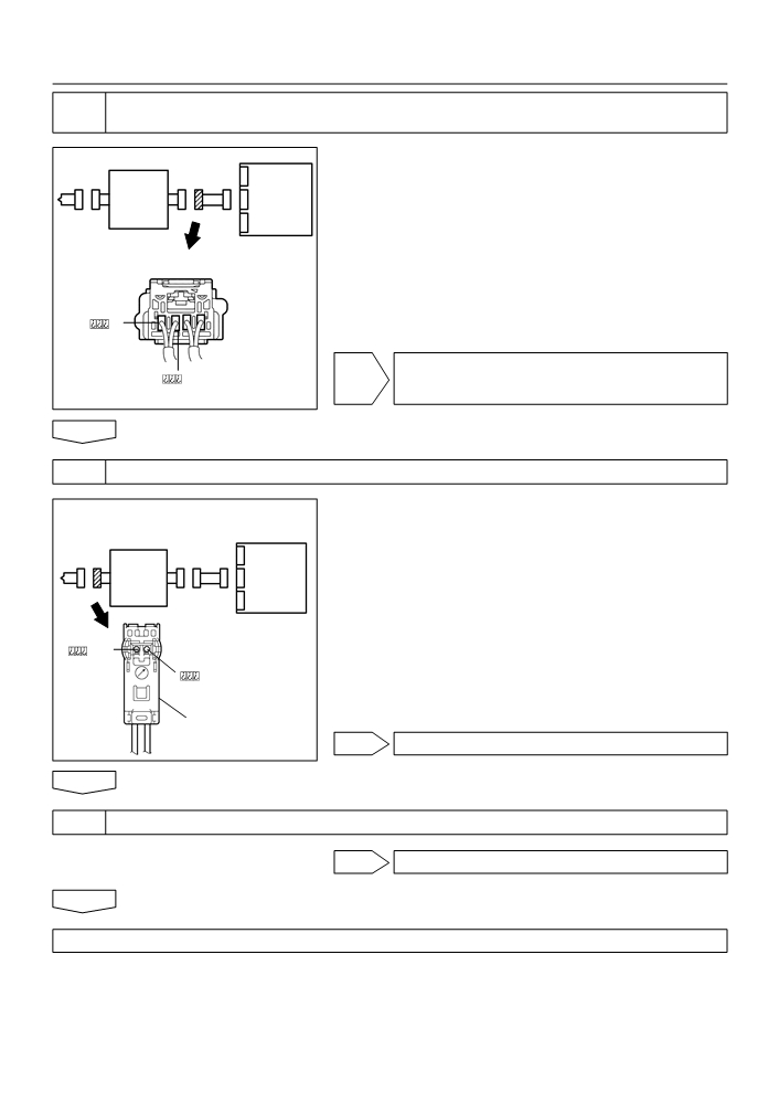
1
CHECK D SQUIB CIRCUIT(AIRBAG SENSOR ASSY CENTER - HORN BUTTON
ASSY)
(a) Disconnect the negative (-) terminal cable from the bat-
tery, and wait at least for 90 seconds.
(b) Disconnect the connector between the airbag sensor
Airbag
D Squib
Spiral
Sensor
assy center and the horn button assy.
Cable
Assy
(c)
For the black connector (on the spiral cable sub-assy
Sub-Assy
Center
side) between the horn button assy and the spiral cable
sub-assy, measure the resistance between D2+ and
body ground.
OK:
Resistance: 1 M W or Higher
Color: Black
H01001
C89244
H41475
NG Go to step 5
OK

05-563
DIAGNOSTICS
- SUPPLEMENTAL RESTRAINT SYSTEM (April, 2003)
2
CHECK AIR BAG SENSOR ASSY CENTER
SST
09843-18040
(a) Connect the connector to the airbag sensor assy center.
(b) Using a service wire, connect D2+ and D2- of the black
Airbag
D Squib
connector (on the spiral cable sub-assy side) between
Spiral
Sensor
Cable
the horn button assy and the spiral cable sub-assy.
Assy
Sub-Assy
(c)
Connect the negative (-) terminal cable to the battery,
Center
and wait at least for 2 seconds.
(d) Turn the ignition switch to ON, and wait t least for 20 se-
conds.
(e) Clear the DTC stored in memory (See page 05-424).
(f)
Turn the ignition switch to LOCK, and wait at least for 20
seconds.
Color: Black
(g) Turn the ignition switch to ON, and wait at least for 20 se-
DTC B1182/19
conds.
DLC3
(h) Check the DTC (See page 05-424).
OK:
DTC B1182/19 is not output.
CG Tc
HINT:
H01002
Codes other than code B1182/19 may be output at this time, but
C89252
H10600
C91338
H42141
they are not relevant to this check.
NG REPLACE AIR BAG SENSOR ASSY CENTER
OK

05-564
DIAGNOSTICS
- SUPPLEMENTAL RESTRAINT SYSTEM (April, 2003)
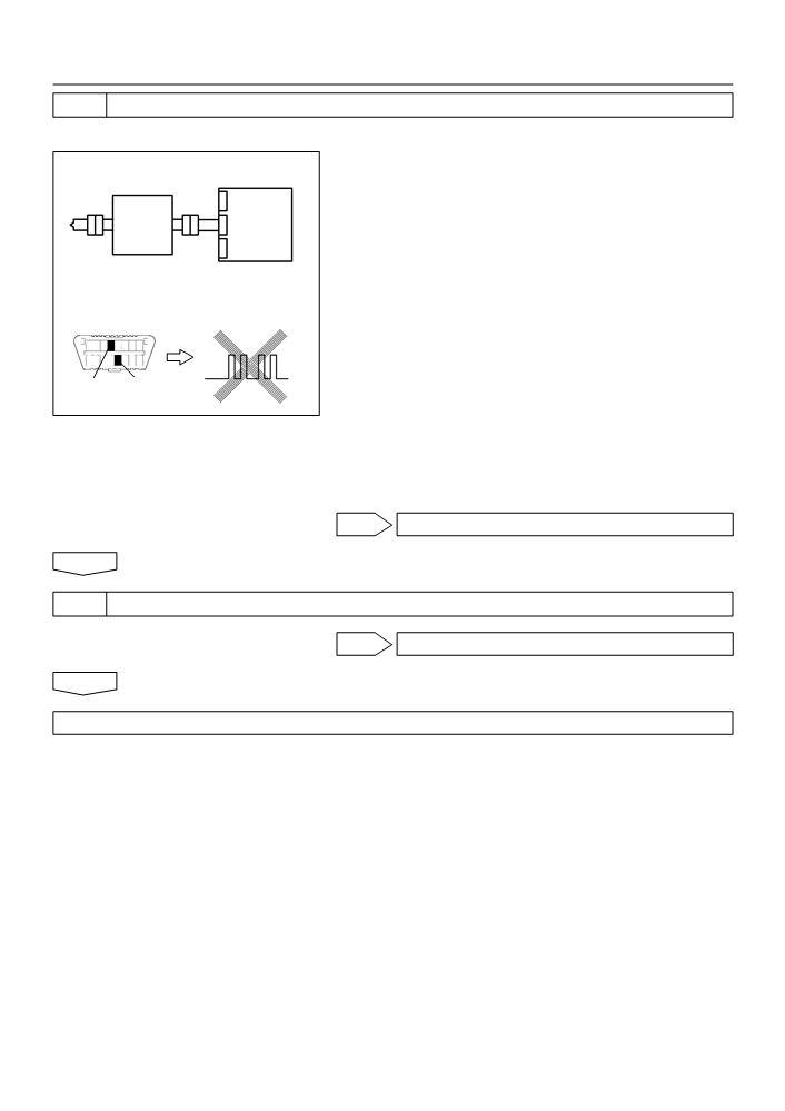
3
CHECK D SQUIB
SST
09843-18040
(a) Turn the ignition switch to LOCK.
(b) Disconnect the negative (-) terminal cable from the bat-
Airbag
D Squib
tery, and wait at least for 90 seconds.
Spiral
Sensor
(c)
Connect the horn button assy connectors.
Cable
Assy
Sub-Assy
(d) Connect the negative (-) terminal cable to the battery,
Center
and wait at least for 2 seconds.
(e) Turn the ignition switch to ON, and wait at least for 20 se-
conds.
(f)
Clear the DTC stored in memory (See page 05-424).
DLC3
DTC B1182/19
(g) Turn the ignition switch to LOCK, and wait at least for 20
seconds.
(h) Turn the ignition switch to ON, and wait at least for 20 se-
CG Tc
conds.
H01003
H10600
C89253
H42142
(i)
Check the DTC (See page 05-424).
OK:
DTC B1182/19 is not output.
HINT:
Codes other than code B1182/19 may be output at this time, but
they are not relevant to this check.
NG REPLACE HORN BUTTON ASSY
OK
4
USE SIMULATION METHOD TO CHECK
NG Go to step 1
OK
REPLACE ALL SRS COMPONENTS INCLUDING THE WIRE HARNESS
05-565
DIAGNOSTICS
- SUPPLEMENTAL RESTRAINT SYSTEM (April, 2003)
5
CHECK INSTRUMENT PANEL WIRE(AIRBAG SENSOR ASSY CENTER - SPIRAL
CABLE SUB-ASSY)
(a) Disconnect the connector of the instrument panel wire.
Airbag
(b) For the connector (on the spiral cable sub-assy side) be-
D Squib
Spiral
Sensor
tween the airbag sensor assy center and the spiral cable
Cable
Assy
sub-assy, measure the resistance between D2+ and
Sub-Assy
Center
body ground.
OK:
Resistance: 1 M W or Higher
NG REPAIR OR REPLACE INSTRUMENT PANEL
WIRE(AIRBAG SENSOR ASSY CENTER - SPI-
H01004
RAL CABLE SUB-ASSY)
H41424
H41478
OK
6
CHECK SPIRAL CABLE SUB-ASSY
(a) For the black connector (on the spiral cable sub-assy
side) between the horn button assy and the spiral cable
sub-assy, measure the resistance between D2+ and
D Squib
Airbag
Spiral
body ground.
Sensor
Cable
OK:
Assy
Sub-Assy
Resistance: 1 M W or Higher
Center
Color: Black
H01000
NG REPLACE SPIRAL CABLE SUB-ASSY
C89244
H41479
OK
7
USE SIMULATION METHOD TO CHECK
NG Go to step 1
OK
REPLACE ALL SRS COMPONENTS INCLUDING THE WIRE HARNESS

05-566
DIAGNOSTICS
- SUPPLEMENTAL RESTRAINT SYSTEM (April, 2003)
055ZO-04
DTC
B1183/22
SHORT IN D SQUIB (2ND STEP) CIRCUIT
(TO B+)
CIRCUIT DESCRIPTION
The D squib (2nd step) circuit consists of the airbag sensor assy center, spiral cable sub-assy and horn but-
ton assy.
It causes the SRS to deploy when the SRS deployment conditions are satisfied.
DTC B1183/22 is recorded when a B+ short is detected in the D squib (2nd step) circuit.
DTC No.
DTC Detecting Condition
Trouble Area
F Short circuit in D squib (2nd step) wire harness (to B+)
F Horn button assy (D squib, 2nd step)
F D squib (2nd step) malfunction
F Spiral cable sub-assy
B1183/22
F Spiral cable sub-assy malfunction
F Airbag sensor assy center
F Airbag sensor assy center malfunction
F Instrument panel wire
WIRING DIAGRAM
See page 05-424.
CIRCUIT INSPECTION
1
CHECK D SQUIB CIRCUIT(AIRBAG SENSOR ASSY CENTER - HORN BUTTON
ASSY)
(a) Disconnect the negative (-) terminal cable from the bat-
tery, and wait at least for 90 seconds.
(b) Disconnect the connectors between the airbag sensor
D Squib
Airbag
Spiral
assy center and the horn button assy.
Sensor
Cable
(c)
Connect the negative (-) terminal cable to the battery,
Assy
Sub-Assy
Center
and wait at least for 2 seconds.
(d) Turn the ignition switch to ON.
(e) For the black connector (on the spiral cable sub-assy
side) between the horn button assy and the spiral cable
sub-assy, measure the voltage between D2+ and body
ground.
OK:
Color: Black
Voltage: Below 1 V
H01001
C89244
H41475
NG Go to step 5
OK

05-567
DIAGNOSTICS
- SUPPLEMENTAL RESTRAINT SYSTEM (April, 2003)
2
CHECK AIR BAG SENSOR ASSY CENTER
SST
09843-18040
(a) Turn the ignition switch to LOCK.
(b) Disconnect the negative (-) terminal cable from the bat-
D Squib
Airbag
tery, and wait at least for 90 seconds.
Spiral
Sensor
(c)
Connect the connector to the airbag sensor assy center.
Cable
Assy
Sub-Assy
(d) Using a service wire, connect D2+ and D2- of the black
Center
connector (on the spiral cable sub-assy side) between
the horn button assy and the spiral cable sub-assy.
(e) Connect the negative (-) terminal cable to the battery,
and wait at least for 2 seconds.
(f)
Turn the ignition switch to ON, and wait at least for 20 se-
conds.
Color: Black
(g) Clear the DTC stored in memory (See page 05-424).
(h) Turn the ignition switch to LOCK, and wait at least for 20
DLC3
DTC B1183/22
seconds.
(i)
Turn the ignition switch to ON, and wait at least for 20 se-
conds.
CG Tc
(j)
Check the DTC (See page 05-424).
H01002
OK:
C89252
H10600
C91342
H42143
DTC B1183/22 is not output.
HINT:
Codes other than code B1183/22 may be output at this time, but
they are not relevant to this check.
NG REPLACE AIR BAG SENSOR ASSY CENTER
OK
05-568
DIAGNOSTICS
- SUPPLEMENTAL RESTRAINT SYSTEM (April, 2003)
3
CHECK D SQUIB
SST
09843-18040
(a) Turn the ignition switch to LOCK.
(b) Disconnect the negative (-) terminal cable from the bat-
Airbag
tery, and wait at least for 90 seconds.
D Squib
Spiral
Sensor
(c)
Connect the horn button assy connectors.
Cable
Sub-Assy
Assy
(d) Connect the negative (-) terminal cable to the battery,
Center
and wait at least for 2 seconds.
(e) Turn the ignition switch to ON, and wait at least for 20 se-
conds.
(f)
Clear the DTC stored in memory (See page 05-424).
DTC B1183/22
DLC3
(g) Turn the ignition switch to LOCK, and wait at least for 20
seconds.
(h) Turn the ignition switch to ON, and wait at least for 20 se-
CG Tc
conds.
H01003
H10600
C91342
H42144
(i)
Check the DTC (See page 05-424).
OK:
DTC B1183/22 is not output.
HINT:
Codes other than code B1183/22 may be output at this time, but
they are not relevant to this check.
NG REPLACE HORN BUTTON ASSY
OK
4
USE SIMULATION METHOD TO CHECK
NG Go to step 1
OK
REPLACE ALL SRS COMPONENTS INCLUDING THE WIRE HARNESS

05-569
DIAGNOSTICS
- SUPPLEMENTAL RESTRAINT SYSTEM (April, 2003)
5
CHECK INSTRUMENT PANEL WIRE(AIRBAG SENSOR ASSY CENTER - SPIRAL
CABLE SUB-ASSY)
(a) Turn the ignition switch to LOCK.
Airbag
(b) Disconnect the connector of the instrument panel wire.
D Squib
Spiral
Sensor
(c)
Turn the ignition switch to ON.
Cable
Assy
(d) For the connector (on the spiral cable sub-assy side) be-
Sub-Assy
Center
tween the horn button assy and the spiral cable sub-assy,
measure the voltage between D2+ and body ground.
OK:
Voltage: Below 1 V
H01004
H41424
H41478
NG REPAIR OR REPLACE INSTRUMENT PANEL
WIRE(AIRBAG SENSOR ASSY CENTER - SPI-
RAL CABLE SUB-ASSY)
OK
6
CHECK SPIRAL CABLE SUB-ASSY
(a) For the black connector (on the spiral cable sub-assy
side) between the horn button assy and the spiral cable
sub-assy, measure the voltage between D2+ and body
Airbag
D Squib
Spiral
ground.
Sensor
Cable
OK:
Assy
Sub-Assy
Voltage: Below 1 V
Center
Color: Black
H01000
C89244
H41479
NG REPLACE SPIRAL CABLE SUB-ASSY
OK
7
USE SIMULATION METHOD TO CHECK
NG Go to step 1
OK
REPLACE ALL SRS COMPONENTS INCLUDING THE WIRE HARNESS

05-570
DIAGNOSTICS
- SUPPLEMENTAL RESTRAINT SYSTEM (April, 2003)
055ZP-04
DTC
B1185/57
SHORT IN P SQUIB (2ND STEP) CIRCUIT
CIRCUIT DESCRIPTION
The P squib (2nd step) circuit consists of the airbag sensor assy center and instrument panel passenger
airbag assy.
It causes the SRS to deploy when the SRS deployment conditions are satisfied.
DTC B1185/57 is recorded when a short is detected in the P squib (2nd step) circuit.
DTC No.
DTC Detecting Condition
Trouble Area
F Short circuit between P2+ wire harness and P2- wire
F Instrument panel passenger airbag assy (P squib, 2nd step)
harness of squib.
B1185/57
F Airbag sensor assy center
F P squib (2nd step) malfunction
F Instrument panel wire
F Airbag sensor assy center malfunction
WIRING DIAGRAM
Airbag Sensor Assy Center
A15
P Squib (2nd step)
8
P+
Y-GR
A13
P2+
3
7
P-
Y-P
A13
P2-
4
H01454

05-571
DIAGNOSTICS
- SUPPLEMENTAL RESTRAINT SYSTEM (April, 2003)
INSPECTION PROCEDURE
1
CHECK P SQUIB CIRCUIT(AIRBAG SENSOR ASSY CENTER - INSTRUMENT
PANEL PASSENGER AIRBAG ASSY)
(a) Disconnect the negative (-) terminal cable from the bat-
tery, and wait at least for 90 seconds.
(b) Disconnect the connectors between the airbag sensor
P Squib
Airbag
assy center and the instrument panel passenger airbag
Sensor
assy.
Assy
Center
(c)
Release the airbag activation prevention mechanism of
the connector (on the airbag sensor assy center side) be-
tween the airbag sensor assy center and the instrument
panel passenger airbag assy (See page 05-424).
(d) For the connector (on the instrument panel passenger air-
P2-
bag assy side) between the airbag sensor assy center
and the instrument panel passenger airbag assy, mea-
sure the resistance between P2+ and P2-.
R14286
P2+
H41424
H41932
OK:
Resistance: 1 M W or Higher
NG REPAIR OR REPLACE INSTRUMENT PANEL
WIRE
OK
2
CHECK AIR BAG SENSOR ASSY CENTER
SST
09843-18040
(a) Connect the connector to the airbag sensor assy center.
(b) Connect the negative (-) terminal cable to the battery,
Airbag
P Squib
and wait at least for 2 seconds.
Sensor
Assy
(c)
Turn the ignition switch to ON, and wait at least for 20 se-
Center
conds.
(d) Clear the DTC stored in memory (See page 05-424).
(e) Turn the ignition switch to LOCK, and wait at least for 20
seconds.
DLC3
DTC B1185/57
(f)
Turn the ignition switch to ON, and wait at least for 20 se-
conds.
(g) Check the DTC (See page 05-424).
OK:
CG Tc
DTC B1185/57 is not output.
H01023
H10600
H16840
H41979
HINT:
Codes other than code B1185/57 may be output at this time, but
they are not relevant to this check.
NG REPLACE AIR BAG SENSOR ASSY CENTER
OK

05-572
DIAGNOSTICS
- SUPPLEMENTAL RESTRAINT SYSTEM (April, 2003)
3
CHECK P SQUIB
SST
09843-18040
(a) Turn the ignition switch to LOCK.
(b) Disconnect the negative (-) terminal cable from the bat-
Airbag
P Squib
tery, and wait at least for 90 seconds.
Sensor
(c)
Connect the instrument panel passenger airbag assy
Assy
Center
connector.
(d) Connect the negative (-) terminal cable to the battery,
and wait at least for 2 seconds.
(e) Turn the ignition switch to ON, and wait at least for 20 se-
DLC3
DTC B1185/57
conds.
(f)
Clear the DTC stored in memory (See page 05-424).
(g) Turn the ignition switch to LOCK, and wait at least for 20
seconds.
CG Tc
(h) Turn the ignition switch to ON, and wait at least for 20 se-
H01024
H10600
H16840
H41980
conds.
(i)
Check the DTC (See page 05-424).
OK:
DTC B1185/57 is not output.
HINT:
Codes other than code B1185/57 may be output at this time, but
they are not relevant to this check.
NG REPLACE INSTRUMENT PANEL PASSENGER
AIR BAG ASSY
OK
USE SIMULATION METHOD TO CHECK

05-573
DIAGNOSTICS
- SUPPLEMENTAL RESTRAINT SYSTEM (April, 2003)
055ZQ-04
DTC
B1186/58
OPEN IN P SQUIB (2ND STEP) CIRCUIT
CIRCUIT DESCRIPTION
The P squib (2nd step) circuit consists of the airbag sensor assy center and instrument panel passenger
airbag assy.
It causes the SRS to deploy when the SRS deployment conditions are satisfied.
DTC B1186/58 is recorded when an open is detected in the P squib circuit.
DTC No.
DTC Detecting Condition
Trouble Area
F Open circuit in P2+ wire harness or P2- wire harness of
F Instrument panel passenger airbag assy (P squib, 2nd step)
squib (2nd step)
B1186/58
F Airbag sensor assy center
F P squib (2nd step) malfunction
F Instrument panel wire
F Airbag sensor assy center malfunction
WIRING DIAGRAM
See page 05-570.
INSPECTION PROCEDURE
1
CHECK P SQUIB CIRCUIT(AIRBAG SENSOR ASSY CENTER - INSTRUMENT
PANEL PASSENGER AIRBAG ASSY)
(a) Disconnect the negative (-) terminal cable from the bat-
tery, and wait at least for 90 seconds.
(b) Disconnect the connectors between the airbag sensor
P Squib
Airbag
assy center and the instrument panel passenger airbag
Sensor
Assy
assy.
Center
(c)
For the connector (on the instrument panel passenger air-
bag assy side) between the airbag sensor assy center
and the instrument panel passenger airbag assy, mea-
sure the resistance between P2+ and P2-.
OK:
P2-
Resistance: Below 1
W
R14286
P2+
H41424
H41932
NG REPAIR OR REPLACE INSTRUMENT PANEL
WIRE
OK

05-574
DIAGNOSTICS
- SUPPLEMENTAL RESTRAINT SYSTEM (April, 2003)
2
CHECK AIR BAG SENSOR ASSY CENTER
SST
09843-18040
(a) Connect the connector to the airbag sensor assy center.
(b) Using a service wire, connect P2+ and P2- of the connec-
P Squib
Airbag
tor (on the instrument panel passenger airbag assy side)
Sensor
between the airbag sensor assy center and the instru-
Assy
ment panel passenger airbag assy.
Center
(c)
Connect the negative (-) terminal cable to the battery,
and wait at least for 2 seconds.
(d) Turn the ignition switch to ON, and wait at least for 20 se-
conds.
(e) Clear the DTC stored in memory (See page 05-424).
(f)
Turn the ignition switch to LOCK, and wait at least for 20
seconds.
(g) Turn the ignition switch to ON, and wait at least for 20 se-
DLC3
DTC B1186/58
conds.
(h) Check the DTC (See page 05-424).
OK:
DTC B1186/58 is not output.
CG Tc
HINT:
H01023
H16853
H10600
H16841
H41981
Codes other than code B1186/58 may be output at this time, but
they are not relevant to this check.
NG REPLACE AIR BAG SENSOR ASSY CENTER
OK

05-575
DIAGNOSTICS
- SUPPLEMENTAL RESTRAINT SYSTEM (April, 2003)
3
CHECK P SQUIB
SST
09843-18040
(a) Turn the ignition switch to LOCK.
(b) Disconnect the negative (-) terminal cable from the bat-
P Squib
Airbag
tery, and wait at least for 90 seconds.
Sensor
(c)
Connect the instrument panel passenger airbag assy
Assy
connector.
Center
(d) Connect the negative (-) terminal cable to the battery,
and wait at least for 2 seconds.
(e) Turn the ignition switch to ON, and wait at least for 20 se-
DLC3
DTC B1186/58
conds.
(f)
Clear the DTC stored in memory (See page 05-424).
(g) Turn the ignition switch to LOCK, and wait at least for 20
seconds.
CG Tc
(h) Turn the ignition switch to ON, and wait at least for 20 se-
H01024
H10600
H16841
H41982
conds.
(i)
Check the DTC (See page 05-424).
OK:
DTC B1186/58 is not output.
HINT:
Codes other than code B1186/58 may be output at this time, but
they are not relevant to this check.
NG REPLACE INSTRUMENT PANEL PASSENGER
AIR BAG ASSY
OK
USE SIMULATION METHOD TO CHECK

05-576
DIAGNOSTICS
- SUPPLEMENTAL RESTRAINT SYSTEM (April, 2003)
055ZR-04
DTC
B1187/55
SHORT IN P SQUIB (2ND STEP) CIRCUIT
(TO GROUND)
CIRCUIT DESCRIPTION
The P squib (2nd step) circuit consists of the airbag sensor assy center and instrument panel passenger
airbag assy.
It causes the SRS to deploy when the SRS deployment conditions are satisfied.
DTC B1187/55 is recorded when ground short is detected in the P squib (2nd step) circuit.
DTC No.
DTC Detecting Condition
Trouble Area
F Short circuit in P squib (2nd step) wire harness (to ground)
F Instrument panel passenger airbag assy (P squib, 2nd step)
B1187/55
F P squib malfunction
F Airbag sensor assy center
F Airbag sensor assy center malfunction
F Instrument panel wire
WIRING DIAGRAM
See page 05-570.
INSPECTION PROCEDURE
1
CHECK P SQUIB CIRCUIT(AIRBAG SENSOR ASSY CENTER - INSTRUMENT
PANEL PASSENGER AIRBAG ASSY)
(a) Disconnect the negative (-) terminal cable from the bat-
tery, and wait at least for 90 seconds.
(b) Disconnect the connector between the airbag sensor
P Squib
Airbag
assy center and the instrument panel passenger airbag
Sensor
Assy
assy.
Center
(c)
For the connector (on the instrument panel passenger air-
bag assy side) between the airbag sensor assy center
and the instrument panel passenger airbag assy, mea-
sure the resistance between P2+ and body ground.
OK:
P2-
Resistance: 1 M W or Higher
R14286
P2+
H41424
H41932
NG REPAIR OR REPLACE INSTRUMENT PANEL
WIRE
OK