Toyota Corolla (2004+). Manual - part 73

05-547
DIAGNOSTICS
- SUPPLEMENTAL RESTRAINT SYSTEM (April, 2003)
8
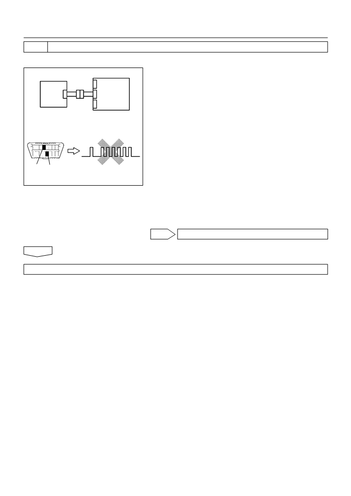
CHECK ENGINE ROOM MAIN WIRE HARNESS(OPEN)(CONNECTOR - AIRBAG
FRONT RH SENSOR)
SST
09843-18040
(a) Disconnect the connectors between the engine room
Engine Room
main wire and the instrument panel wire.
Main Wire
Airbag
Airbag
(b) Using a service wire, connect +SR and -SR of the engine
Sensor
Front
room main wire connector (on the airbag front RH sensor
Assy
RH Sensor
side) between the airbag sensor assy center and the air-
Center
bag front RH sensor.
(c)
For the engine room main wire connector (on the airbag
sensor assy center side) between the airbag sensor assy
center and the airbag front RH sensor, measure the resis-
tance between the +SR and -SR.
OK:
Resistance: Below 1
W
-SR
+SR
NG REPAIR OR REPLACE ENGINE ROOM MAIN
H41945
WIRE
OK
REPAIR OR REPLACE INSTRUMENT PANEL WIRE

05-548
DIAGNOSTICS
- SUPPLEMENTAL RESTRAINT SYSTEM (April, 2003)
057UT-02
DTC
B1158/16
FRONT AIRBAG SENSOR (LH)
MALFUNCTION
DTC
B1159/16
FRONT AIRBAG SENSOR (LH)
MALFUNCTION
CIRCUIT DESCRIPTION
The airbag sensor front LH circuit consists of the airbag sensor assy center and airbag sensor front LH.
DTC B1158/B1159/16 is recorded when malfunction is detected in the airbag sensor front LH circuit.
DTC No.
DTC Detecting Condition
Trouble Area
F Airbag sensor front LH
F Airbag sensor assy center
B1158/B1159/16
F Airbag sensor front LH malfunction
F Instrument panel wire
F Engine room main wire
WIRING DIAGRAM
A5
Airbag Sensor Front LH
Airbag Sensor Assy Center
3
15
W-R
W-R
+SL
IA1
A13
+SL
2
4
26
BR
BR
-SL
IA1
A13
-SL
1
H02750

05-549
DIAGNOSTICS
- SUPPLEMENTAL RESTRAINT SYSTEM (April, 2003)
INSPECTION PROCEDURE
1
CHECK FRONT AIRBAG SENSOR (LH) CIRCUIT (TO B+)(AIRBAG SENSOR ASSY
CENTER - AIRBAG SENSOR FRONT LH)
(a) Disconnect the negative (-) terminal cable from the bat-
Airbag
tery, and wait at least for 90 seconds.
Airbag
Sensor
(b) Disconnect the connectors between the airbag sensor
Sensor
Assy
assy center and the airbag sensor front LH.
Front LH
Center
(c)
Connect the negative (-) terminal cable to the battery,
and wait at least for 2 seconds.
(d) Turn the ignition switch to ON.
(e) For the connector (on the airbag sensor assy center side)
between the airbag sensor front LH and the airbag sensor
+SL
assy center, measure the voltage between body ground
and each of +SL and -SL.
-SL
OK:
Voltage: Below 1 V
H03355
C81408
H40069
NG Go to step 6
OK
2
CHECK FRONT AIRBAG SENSOR(LH) CIRCUIT(TO GROUND)(AIRBAG SENSOR
ASSY CENTER - AIRBAG SENSOR FRONT LH)
(a) Turn the ignition switch to LOCK.
Airbag
(b) Disconnect the negative (-) terminal cable from the bat-
Airbag
Sensor
tery, and wait at least for 90 seconds.
Sensor
Assy
(c)
For the connector (on the airbag sensor assy center side)
Front LH
Center
between the airbag sensor front LH and the airbag sensor
assy center, measure the resistance between body
ground and each of +SL and -SL.
OK:
Resistance: 1 M W or Higher
+SL
-SL
H03355
C81408
H40069
NG Go to step 7
OK

05-550
DIAGNOSTICS
- SUPPLEMENTAL RESTRAINT SYSTEM (April, 2003)
3
CHECK FRONT AIRBAG SENSOR (LH) CIRCUIT(OPEN)(AIRBAG SENSOR ASSY
CENTER - AIRBAG SENSOR FRONT LH)
(a) Using a service wire, connect +SL and -SL of the connec-
Airbag
tor (on the airbag sensor front LH side) between the air-
Airbag
Sensor
bag sensor assy center and the airbag sensor front LH.
Sensor
Assy
(b) For the connector (on the airbag sensor assy center side)
Front LH
Center
between the airbag sensor front LH and the airbag sensor
assy center, measure the resistance between +SL and
-SL.
OK:
+SL
Resistance: Below 1
W
-SL
H03353
H03360 H08016
H41802
NG Go to step 8
OK
4
INSPECT AIR BAG SENSOR FRONT LH
(a) For the connector of the airbag sensor front LH, measure
the resistance between +SL and -SL.
OK:
Resistance: 820
W
+SL
-SL
C54743
H40071
NG REPLACE AIR BAG SENSOR FRONT LH
OK
05-551
DIAGNOSTICS
- SUPPLEMENTAL RESTRAINT SYSTEM (April, 2003)
5
CHECK AIR BAG SENSOR ASSY CENTER
SST
09843-18040
(a) Disconnect the negative (-) terminal cable from the bat-
tery, and wait at least for 90 seconds.
Airbag
Airbag
(b) Connect the airbag sensor front LH connector and airbag
Sensor
Sensor
Assy
sensor assy center connector.
Front LH
Center
(c)
Connect the negative (-) terminal cable to the battery,
and wait at least for 2 seconds.
(d) Turn the ignition switch to ON, and wait at least for 20 se-
conds.
DLC3
DTC B1158/B1159/16
(e) Clear the DTC stored in memory (See page 05-424).
(f)
Turn the ignition switch to LOCK, and wait at least for 20
seconds.
(g) Turn the ignition switch to ON, and wait at least for 20 se-
CG Tc
conds.
H02757
H40075
(h) Check the DTC (See page 05-424).
H10600 H01064
OK:
DTC B1158/B1159/16 is not output.
HINT:
Codes other than code B1158/B1159/16 may be output at this
time, but they are not relevant to this check.
NG REPLACE AIR BAG SENSOR ASSY CENTER
OK
USE SIMULATION METHOD TO CHECK

05-552
DIAGNOSTICS
- SUPPLEMENTAL RESTRAINT SYSTEM (April, 2003)
6
CHECK ENGINE ROOM MAIN WIRE HARNESS (TO B+)(CONECTOR - AIRBAG
SENSOR FRONT LH)
(a) Turn the ignition switch to LOCK.
(b) Disconnect the negative (-) terminal cable from the bat-
Airbag
tery, and wait at least for 90 seconds.
Airbag
Sensor
Sensor
(c)
Disconnect the connector between the engine room main
Assy
Front LH
wire and the instrument panel wire.
Center
(d) Connect the negative (-) terminal to the battery, and wait
Engine Room
at least for 2 seconds.
Main Wire
(e) Turn the ignition switch to ON.
(f)
For the engine room main wire connector (on the airbag
sensor assy center side) between the airbag sensor assy
+SL
center and the airbag sensor front LH, measure the volt-
-SL
age between body ground and each of +SL and -SL.
OK:
H03354
H40556
H40558
Voltage: Below 1 V
NG REPAIR OR REPLACE ENGINE ROOM MAIN
WIRE
OK
REPAIR OR REPLACE INSTRUMENT PANEL WIRE
7
CHECK ENGINE ROOM MAIN WIRE HARNESS (TO GROUND)(CONNECTOR -
AIRBAG SENSOR FRONT LH)
(a) Disconnect the connectors between the engine room
main wire and the instrument panel wire.
Airbag
Airbag
(b) For the engine room main wire connector (on the airbag
Sensor
Sensor
sensor assy center side) between the airbag sensor assy
Assy
Front LH
center and the airbag sensor front LH, measure the resis-
Center
tance between body ground and each of +SL and -SL.
Engine Room
OK:
Main Wire
Resistance: 1 M W or Higher
-SL
+SL
H03354
H40556
H40558
NG REPAIR OR REPLACE ENGINE ROOM MAIN
WIRE
OK
REPAIR OR REPLACE INSTRUMENT PANEL WIRE

05-553
DIAGNOSTICS
- SUPPLEMENTAL RESTRAINT SYSTEM (April, 2003)
8
CHECK ENGINE ROOM MAIN WIRE HARNESS(OPEN)(CONNECTOR - AIRBAG
SENSOR FRONT LH)
(a) Disconnect the connectors between the engine room
Engine Room
main wire and the instrument panel wire.
Main Wire
Airbag
Airbag
(b) Using a service wire, connect +SL and -SL of the engine
Sensor
Sensor
room main wire connector (on the airbag sensor front LH
Assy
Front LH
side) between the airbag sensor assy center and the air-
Center
bag sensor front LH.
(c)
For the engine room main wire connector (on the airbag
sensor assy center side) between the airbag sensor assy
center and the airbag sensor front LH, measure the resis-
tance between +SL and -SL.
OK:
Resistance: Below 1
W
-SL
+SL
H03352
NG REPAIR OR REPLACE ENGINE ROOM MAIN
H08016
H40556
H41801
WIRE
OK
REPAIR OR REPLACE INSTRUMENT PANEL WIRE

05-554
DIAGNOSTICS
- SUPPLEMENTAL RESTRAINT SYSTEM (April, 2003)
055ZL-04
DTC
B1180/17
SHORT IN D SQUIB (2ND STEP) CIRCUIT
CIRCUIT DESCRIPTION
The D squib circuit consists of the airbag sensor assy center, spiral cable sub-assy and horn button assy.
It causes the SRS to deploy when the SRS deployment conditions are satisfied.
DTC B1180/17 is recorded when a short is detected in the D squib circuit (2nd step).
DTC No.
DTC Detecting Condition
Trouble Area
F Short circuit between D2+ wire harness and D2- wire
F Horn button assy (D squib, 2nd step)
harness of squib (2nd step)
F Spiral cable sub-assy
B1180/17
F D squib (2nd step) malfunction
F Airbag sensor assy center
F Spiral cable sub-assy malfunction
F Instrument panel wire
F Airbag sensor assy center malfunction
WIRING DIAGRAM
Airbag Sensor Assy Center
A16
D Squib (2nd step)
16
D+
Y-V
A13
D2+
4
17
D-
Y-O
A13
D2-
3
Spiral Cable
Sub-Assy
H01451

05-555
DIAGNOSTICS
- SUPPLEMENTAL RESTRAINT SYSTEM (April, 2003)
INSPECTION PROCEDURE
1
CHECK D SQUIB CIRCUIT(AIRBAG SENSOR ASSY CENTER - HORN BUTTON
ASSY)
(a) Disconnect the negative (-) terminal cable from the bat-
tery, and wait at least for 90 seconds.
(b) Disconnect the connectors between the airbag sensor
Airbag
D Squib
Spiral
assy center and the horn button assy.
Sensor
Cable
Assy
(c)
Release the airbag activation prevention mechanism of
Sub-Assy
Center
the connector (on the airbag sensor assy center side) be-
tween the airbag sensor assy center and the spiral cable
sub-assy (See page 05-424).
(d) For the black connector (on the spiral cable sub-assy
side ) between the horn button assy and the spiral cable
sub-assy, measure the resistance between D2+ and
D2-.
Color: Black
OK:
H01001
C89244
H41475
Resistance: 1 M W or Higher
NG Go to step 4
OK
2
CHECK AIR BAG SENSOR ASSY CENTER
SST
09843-18040
(a) Connect the connector to the airbag sensor assy center.
(b) Connect the negative (-) terminal cable to the battery,
Airbag
D Squib
Spiral
and wait at least for 2 seconds.
Sensor
Cable
Assy
(c)
Turn the ignition switch to ON, and wait at least for 20 se-
Sub-Assy
Center
conds.
(d) Clear the DTC stored in memory (See page 05-424).
(e) Turn the ignition switch to LOCK, and wait at least for 20
seconds.
(f)
Turn the ignition switch to ON, and wait at least for 20 se-
DTC B1180/17
DLC3
conds.
(g) Check the DTC (See page 05-424).
OK:
DTC B1180/17 is not output.
CG Tc
H01002
H10600
C89246
H42137
HINT:
Codes other than code B1180/17 may be output at this time, but
they are not relevant to this check.
NG REPLACE AIR BAG SENSOR ASSY CENTER
OK

05-556
DIAGNOSTICS
- SUPPLEMENTAL RESTRAINT SYSTEM (April, 2003)
3
CHECK D SQUIB
SST
09843-18040
(a) Turn the ignition switch to LOCK.
(b) Disconnect the negative (-) terminal cable from the bat-
Airbag
D Squib
Spiral
tery, and wait at least for 90 seconds.
Sensor
Cable
Assy
(c)
Connect the horn button assy connectors.
Sub-Assy
Center
(d) Connect the negative (-) terminal cable to the battery,
and wait at least for 2 seconds.
(e) Turn the ignition switch to ON, and wait at least for 20 se-
conds.
DTC B1180/17
(f)
Clear the DTC stored in memory (See page 05-424).
DLC3
(g) Turn the ignition switch to LOCK, and wait at least for 20
seconds.
(h) Turn the ignition switch to ON, and wait at least for 20 se-
CG Tc
conds.
H01003
C89246
H42138
(i)
Check the DTC (See page 05-424).
H10600
OK:
DTC B1180/17 is not output.
HINT:
Codes other than code B1180/17 may be output at this time, but
they are not relevant to this check.
NG REPLACE HORN BUTTON ASSY
OK
USE SIMULATION METHOD TO CHECK
4
CHECK INSTRUMENT PANEL WIRE(AIRBAG SENSOR ASSY CENTER - SPIRAL
CABLE SUB-ASSY)
(a) Disconnect the connector of the instrument panel wire.
Airbag
(b) Release the airbag activation prevention mechanism of
D Squib
Spiral
Sensor
the connector (on the airbag sensor assy center side) be-
Cable
Assy
tween the airbag sensor assy center and the spiral cable
Sub-Assy
Center
sub-assy (See page 05-424).
(c)
For the connector (on the spiral cable sub-assy side) be-
tween the airbag sensor assy center and the spiral cable
sub-assy, measure the resistance between D2+ and
D2-.
OK:
Resistance: 1 M W or Higher
NG REPAIR OR REPLACE INSTRUMENT PANEL
WIRE(AIRBAG SENSOR ASSY CENTER - SPI-
H01004
RAL CABLE SUB-ASSY)
H41424
H41478
OK

05-557
DIAGNOSTICS
- SUPPLEMENTAL RESTRAINT SYSTEM (April, 2003)
5
CHECK SPIRAL CABLE SUB-ASSY
(a) Release the airbag activation prevention mechanism of
the spiral cable sub-assy connector on the airbag sensor
assy center side (See page 05-424).
D Squib
Airbag
Spiral
(b) For the black connector (on the spiral cable sub-assy
Sensor
Cable
side) between the horn button assy and the spiral cable
Assy
Sub-Assy
sub-assy, measure the resistance between D2+ and
Center
D2-.
OK:
Resistance: 1 M W or Higher
Color: Black
H01000
C89244
H41479
NG REPLACE SPIRAL CABLE SUB-ASSY
OK
USE SIMULATION METHOD TO CHECK

05-558
DIAGNOSTICS
- SUPPLEMENTAL RESTRAINT SYSTEM (April, 2003)
055ZM-04
DTC
B1181/18
OPEN IN D SQUIB (2ND STEP) CIRCUIT
CIRCUIT DESCRIPTION
The D squib circuit consists of the airbag sensor assy center, spiral cable sub-assy and horn button assy.
It causes the SRS to deploy when the SRS deployment conditions are satisfied.
DTC B1181/18 is recorded when an open is detected in the D squib circuit (2nd step).
DTC No.
DTC Detecting Condition
Trouble Area
F Open circuit in D+ wire harness or D- wire harness of squib
F Horn button assy (D squib, 2nd step)
F D squib (2nd step) malfunction
F Spiral cable sub-assy
B1181/18
F Spiral cable sub-assy malfunction
F Airbag sensor assy center
F Airbag sensor assy center malfunction
F Instrument panel wire
WIRING DIAGRAM
See page 05-554.
INSPECTION PROCEDURE
1
CHECK D SQUIB CIRCUIT(AIRBAG SENSOR ASSY CENTER - HORN BUTTON
ASSY)
(a) Disconnect the negative (-) terminal cable from the bat-
tery, and wait at least for 90 seconds.
(b) Disconnect the connectors between the horn button assy
D Squib
Airbag
Spiral
and the airbag sensor assy center.
Sensor
Cable
(c)
For the black connector (on the spiral cable sub-assy
Assy
Sub-Assy
side) between the horn button assy and the spiral cable
Center
sub-assy, measure the resistance between D2+ and
D2-.
OK:
Resistance: Below 1
W
Color: Black
H01001
C89244
H41475
NG Go to step 4
OK

05-559
DIAGNOSTICS
- SUPPLEMENTAL RESTRAINT SYSTEM (April, 2003)
2
CHECK AIR BAG SENSOR ASSY CENTER
SST
09843-18040
(a) Connect the connector to the airbag sensor assy center.
(b) Using a service wire, connect D2+ and D2- of the black
D Squib
Airbag
connector (on the spiral cable sub-assy side) between
Spiral
Sensor
Cable
the horn button assy and the spiral cable sub-assy.
Sub-Assy
Assy
(c)
Connect the negative (-) terminal cable to the battery,
Center
and wait at least for 2 seconds.
(d) Turn the ignition switch to ON, and wait at least for 20 se-
conds.
(e) Clear the DTC stored in memory (See page 05-424).
(f)
Turn the ignition switch to LOCK, and wait at least for 20
seconds.
(g) Turn the ignition switch to ON, and wait at least for 20 se-
Color: Black
conds.
DTC B1181/18
(h) Check the DTC (See page 05-424).
DLC3
OK:
DTC B1181/18 is not output.
HINT:
CG Tc
Codes other than code B1181/18 may be output at this time, but
H01002
C89252
H42139
they are not relevant to this check.
H10600
C89253
NG REPLACE AIR BAG SENSOR ASSY CENTER
OK

05-560
DIAGNOSTICS
- SUPPLEMENTAL RESTRAINT SYSTEM (April, 2003)
3
CHECK D SQUIB
SST
09843-18040
(a) Turn the ignition switch to LOCK.
(b) Disconnect the negative (-) terminal cable from the bat-
D Squib
Airbag
tery, and wait at least for 90 seconds.
Spiral
Sensor
Cable
(c)
Connect the horn button assy connectors.
Assy
Sub-Assy
(d) Connect the negative (-) terminal cable to the battery,
Center
and wait at least for 2 seconds.
(e) Turn the ignition switch to ON, and wait at least for 20 se-
conds.
(f)
Clear the DTC stored in memory (See page 05-424).
DLC3
DTC B1181/18
(g) Turn the ignition switch to LOCK, and wait at least for 20
seconds.
(h) Turn the ignition switch to ON, and wait at least for 20 se-
CG Tc
conds.
H01003
H10600
C89253
H42140
(i)
Check the DTC (See page 05-424).
OK:
DTC B1181/18 is not output.
HINT:
Codes other than code B1181/18 may be output at this time, but
they are not relevant to this check.
NG REPLACE HORN BUTTON ASSY
OK
USE SIMULATION METHOD TO CHECK
4
CHECK INSTRUMENT PANEL WIRE(AIRBAG SENSOR ASSY CENTER - SPIRAL
CABLE SUB-ASSY)
(a) Disconnect the connector of the instrument panel wire.
D Squib
Airbag
(b) For the connector (on the spiral cable sub-assy side) be-
Spiral
Sensor
tween the airbag sensor assy center and the spiral cable
Cable
Sub-Assy
Assy
sub-assy, measure the resistance between D2+ and
Center
D2-.
OK:
Resistance: Below 1
W
NG REPAIR OR REPLACE INSTRUMENT PANEL
WIRE(AIRBAG SENSOR ASSY CENTER - SPI-
RAL CABLE SUB-ASSY)
H01004
H41424
H41478
OK

05-561
DIAGNOSTICS
- SUPPLEMENTAL RESTRAINT SYSTEM (April, 2003)
5
CHECK SPIRAL CABLE SUB-ASSY
(a) For the black connector (on the spiral cable sub-assy
side) between the horn button assy and the spiral cable
sub-assy, measure the resistance between D2+ and
D Squib
Airbag
Spiral
D2-.
Sensor
Cable
OK:
Assy
Sub-Assy
Resistance: Below 1
W
Center
Color: Black
H01000
C89244
H41479
NG REPLACE SPIRAL CABLE SUB-ASSY
OK
USE SIMULATION METHOD TO CHECK