Toyota Corolla (2004+). Manual - part 54

05-282
DIAGNOSTICS
- SFI SYSTEM (April, 2003)
7
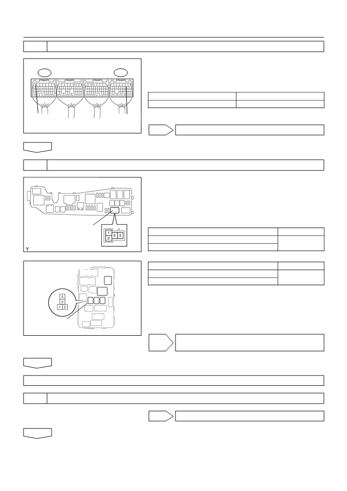
CHECK HARNESS AND CONNECTOR(CIRCUIT OPENING RELAY - FUEL PUMP,
FUEL PUMP - BODY GROUND)
(a) Remove the circuit opening relay from the instrument
Instrument Panel J/B:
panel J/B.
(b) Disconnect the F10 fuel pump connector.
(c)
Check the resistance between the wire harness side con-
nectors.
Standard (Check for open):
Tester Connection
Specified Condition
Circuit Opening
Circuit opening relay (3) - Fuel pump (F10-4)
Below 1 W
Relay
Fuel pump (F10-5) - Body ground
A85429
Standard (Check for short):
Tester Connection
Specified Condition
Wire Harness Side:
Circuit opening relay (3) or Fuel pump (F10-4) - Body ground
10 kW or higher
Fuel Pump Connector
F10
(d) Reconnect the fuel pump connector.
(e) Reinstall the circuit opening relay.
Front View
NG REPAIR OR REPLACE HARNESS OR
A66276
CONNECTOR
OK
REPLACE ECM (See page 10-11)

05-283
DIAGNOSTICS
- SFI SYSTEM (April, 2003)
OBD II scan tool (excluding hand-held tester):
1
CHECK OPERATION OF FUEL PUMP
(a) Turn the ignition switch ON.
(b) Connect between terminals FC and E01 of the ECM con-
E3
E6
nector.
(c)
Check for fuel pressure in the fuel inlet hose when it is
pinched off.
Result: There is pressure in fuel inlet hose.
HINT:
E01 (-)
FC (+)
At this time, you will hear the fuel flowing sound.
ECM Connector
A18294
OK PROCEED TO NEXT CIRCUIT INSPECTION
SHOWN ON PROBLEM SYMPTOMS TABLE
A72879
(See page 05-42)
NG
2
INSPECT ECM POWER SOURCE CIRCUIT (See page 05-273)
NG REPAIR OR REPLACE ECM POWER SOURCE
CIRCUIT
OK
3
INSPECT CIRCUIT OPENING RELAY
(a) Remove the circuit opening relay from the instrument
panel J/B.
(b) Check for continuity in the circuit opening relay.
Standard:
Tester Connection
Specified Condition
1 - 2
Continuity
No continuity
3 - 5
Continuity
(Apply battery voltage to terminals 1 and 2)
E34090
(c)
Reinstall the circuit opening relay.
NG REPLACE CIRCUIT OPENING RELAY
OK
05-284
DIAGNOSTICS
- SFI SYSTEM (April, 2003)
4
INSPECT ECM(FC VOLTAGE)
(a) Turn the ignition switch ON.
(b) Measure the voltage between the terminals of the E3 and
E3
E6
E6 ECM connectors.
Standard:
Tester Connection
Specified Condition
FC (E6-10) - E01 (E3-7)
9 to 14 V
E01 (-)
FC (+)
ECM Connector
A18294
OK REPLACE ECM (See page 10-11)
NG
5
CHECK HARNESS AND CONNECTOR(EFI RELAY - CIRCUIT OPENING RELAY)
Engine Room R/B:
(a) Remove the EFI relay from the engine room R/B.
(b) Remove the circuit opening relay from the instrument
panel J/B.
(c)
Check the resistance between the wire harness side con-
nectors.
Standard (Check for open):
EFI Relay
Tester Connection
Specified Condition
EFI relay (1) - Circuit opening relay (1)
Below 1 W
A65750
EFI relay (3) - Circuit opening relay (5)
Standard (Check for short):
Instrument Panel J/B:
Tester Connection
Specified Condition
EFI relay (1) or Circuit opening relay (1) - Body ground
10 kW or higher
EFI relay (3) or Circuit opening relay (5) - Body ground
(d) Reinstall the circuit opening relay.
(e) Reinstall the EFI relay.
Circuit Opening
Relay
A85429
NG REPAIR OR REPLACE HARNESS AND
CONNECTOR
OK
REPLACE ECM (See page 10-11)
6
INSPECT FUEL PUMP
NG REPAIR OR REPLACE FUEL PUMP
OK

05-285
DIAGNOSTICS
- SFI SYSTEM (April, 2003)
7
CHECK HARNESS AND CONNECTOR(CIRCUIT OPENING RELAY - FUEL
PUMP,FUEL PUMP - BODY GROUND)
(a) Remove the circuit opening relay from the instrument
Instrument Panel J/B:
panel J/B.
(b) Disconnect the F10 fuel pump connector.
(c)
Check the resistance between the wire harness side con-
nectors.
Standard (Check for open):
Tester Connection
Specified Condition
Circuit Opening
Circuit opening relay (3) - Fuel pump (F10-4)
Below 1 W
Relay
Fuel pump (F10-5) - Body ground
A85429
Standard (Check for short):
Tester Connection
Specified Condition
Wire Harness Side
Circuit opening relay (3) or Fuel pump (F10-4) - Body ground
10 kW or higher
Fuel Pump Connector
F10
(d) Reconnect the fuel pump connector.
(e) Reinstall the circuit opening relay.
Front View
NG REPAIR OR REPLACE HARNESS AND
A66276
CONNECTOR
OK
REPLACE ECM (See page 10-11)
05-13
DIAGNOSTICS
- SFI SYSTEM (April, 2003)
05CRJ-02
BASIC INSPECTION
When the malfunction is not confirmed in the DTC check, troubleshooting should be carried out in all the
possible circuits considered as causes of the problem. In many cases, by carrying out the basic engine check
shown in the following flowchart, the location causing the problem can be found quickly and efficiently. There-
fore, using this check is essential in the engine troubleshooting.
1
CHECK BATTERY VOLTAGE
NOTICE:
Carry out this check with the engine stopped and ignition switch OFF.
OK
NG
Voltage
11 V or more
Less than 11 V
NG CHARGE OR REPLACE BATTERY
OK
2
CHECK IF ENGINE WILL CRANK
NG PROCEED TO PROBLEM SYMPTOMS TABLE
ON PAGE 05-42
OK
3
CHECK IF ENGINE STARTS
NG GO TO STEP 7
OK
4
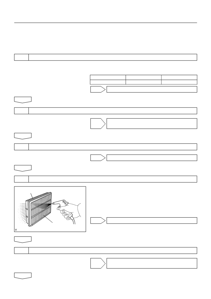
CHECK AIR FILTER
(a) Visually check that the air filter is not excessively dirty or
Outside
oily.
NOTICE:
If necessary, clean the filter with compressed air. First blow
from the inside thoroughly, then blow from the outside of
the filter.
NG CLEAN OR REPLACE
Inside
A66289
OK
5
CHECK IDLE SPEED (See page 14-1)
NG PROCEED TO PROBLEM SYMPTOMS TABLE
ON PAGE 05-42
OK
05-14
DIAGNOSTICS
- SFI SYSTEM (April, 2003)
6
CHECK IGNITION TIMING (See page 14-1)
NG PROCEED TO PAGE 14-1 AND CONTINUE TO
TROUBLESHOOT
OK
PROCEED TO PROBLEM SYMPTOMS TABLE ON PAGE 05-42
7
CHECK FUEL PRESSURE (See page 11-5)
NG PROCEED TO PAGE 11-1 AND CONTINUE TO
TROUBLESHOOT
OK
8
CHECK FOR SPARK (See page 18-1)
NG PROCEED TO PAGE 18-1 AND CONTINUE TO
TROUBLESHOOT
OK
PROCEED TO PROBLEM SYMPTOMS TABLE ON PAGE 05-42

05-25
DIAGNOSTICS
- SFI SYSTEM (April, 2003)
05DIF-01
LIST OF DISABLE A MONITOR
HINT:
This table indicates ECM monitoring status for the items in the upper columns if the DTCs in each line on
the left are being set.
G26588

05-26
DIAGNOSTICS
- SFI SYSTEM (April, 2003)
G26589

05-292
DIAGNOSTICS
- SFI SYSTEM (April, 2003)
059UT-07
MIL CIRCUIT
CIRCUIT DESCRIPTION
The ignition switch provides circuit power and the ECM provides the circuit ground that illuminates the MIL.
MIL operation is checked visually:
It should be illuminated when the ignition is first turned on. If the MIL is off all of the time or on all of the time,
use the procedure below to troubleshoot it. The MIL is used to indicate the ECM’s detection of a vehicle mal-
function. Follow this procedure using the hand-held tester or an OBD II scan tool to determine the cause
of the problem and to check the MIL.
WIRING DIAGRAM
AM2
3
6
B-R
B
IM
IM
ECM
5
11
Instrument
R-Y
E6
W
2
IA4
Panel J/B
I10
Ignition
B-R
Switch
33
1
6
2
Malfunction
Engine
Indicator
MAIN
Room R/B
Lamp
and J/B
1
B-W
1
IA
B
5
IL
32
C9
FL MAIN
Instrument
Combination
Panel J/B
Meter
8
IK
Battery
B-O
A84735
INSPECTION PROCEDURE
HINT:
Troubleshoot each trouble symptom in accordance with the chart below.
MIL remains on
Start inspection from step 1
MIL is not illuminated
Start inspection from step 3

05-293
DIAGNOSTICS
- SFI SYSTEM (April, 2003)
1
CLEAR DTC
(a) Connect the hand-held tester or the OBD II scan tool to the DLC 3.
(b) Turn the ignition switch ON and push the hand-held tester or the OBD II scan tool main switch ON.
(c)
Read the DTC (See page 05-9).
(d) Clear the DTC (See page 05-9).
(e) Check that MIL is not illuminated.
Standard: MIL is not illuminated
OK REPAIR CIRCUIT INDICATED BY OUTPUT
CODE (See page 05-35)
NG
2
CHECK HARNESS AND CONNECTOR(CHECK FOR SHORT IN WIRE HARNESS)
(a) Disconnect the E6 ECM connector.
(b) Turn the ignition switch ON.
E6
(c)
Check that MIL is not illuminated.
Standard: MIL is not illuminated
(d) Reconnect the ECM connector.
ECM Connector
A65748
OK REPLACE ECM (See page 10-11)
NG
CHECK AND REPAIR HARNESS AND CONNECTOR (COMBINATION METER - ECM)
3
CHECK THAT MIL IS ILLUMINATED
(a) Check that MIL is illuminated when turning the ignition switch ON.
Standard: MIL is illuminated
OK SYSTEM OK
NG
4
INSPECT COMBINATION METER ASSY (MIL CIRCUIT)
(a) See the combination meter troubleshooting on page (See page 05-638).
NG REPAIR OR REPLACE BULB OR COMBINATION
METER ASSEMBLY
OK
CHECK AND REPAIR HARNESS AND CONNECTOR (COMBINATION METER - ECM)

05-44
DIAGNOSTICS
- SFI SYSTEM (April, 2003)
05AIH-06
DTC
P0010
CAMSHAFT POSITION ”A” ACTUATOR
CIRCUIT (BANK 1)
CIRCUIT DESCRIPTION
The Variable Valve Timing (VVT) system includes the ECM, the Oil Control Valve (OCV) and the VVT control-
ler. The ECM sends a target ”duty-cycle” control signal to the OCV. This control signal, applied to the OCV,
regulates the oil pressure supplied to the VVT controller. Camshaft timing control is performed based on en-
gine operation conditions such as the intake air volume, throttle position and engine coolant temperature.
The ECM controls the OCV, based on the signals output from the sensors. The VVT controller regulates the
intake camshaft angle using oil pressure through the OCV. As result, the relative position between the cam-
shaft and the crankshaft is optimized, and the engine torque improves, fuel economy improves, and exhaust
emissions decrease under overall driving conditions. Also, the ECM detects the actual valve timing using
signals from the camshaft position sensor and the crankshaft position sensor, and performs the feedback
control. This is how target valve timing is verified by the ECM.
ECM
Crankshaft Position Sensor
Camshaft Timing
Mass Air Flow Sensor
Target Valve Timing
Oil Control
Valve (OCV)
Throttle Position Sensor
Feedback
Duty Control
Engine Coolant Temp. Sensor
Correction
Vehicle Speed Signal
Actual Valve Timing
Camshaft Position Sensor
A71007
DTC No.
DTC Detection Condition
Trouble Area
F Open or short in oil control valve circuit
P0010
Open or short in oil control valve circuit
F Oil control valve
F ECM

05-45
DIAGNOSTICS
-
SFI SYSTEM (April, 2003)
MONITOR DESCRIPTION
After the ECM sends the ”target” duty-cycle signal to the OCV, the ECM monitors the OCV current to estab-
lish an ”actual” duty-cycle. The ECM detects a malfunction and sets a DTC when the actual duty-cycle ratio
varies from the target duty-cycle ratio.
MONITOR STRATEGY
Related DTCs
P0010
VVT oil control valve bank 1 range check
Required sensors/components
OCV
Frequency of operation
Continuous
Duration
1 seconds
MIL operation
Immediately
Sequence of operation
None
TYPICAL ENABLING CONDITIONS
Specification
Item
Minimum
Maximum
The monitor will run whenever the follow-
See ”List of Disable a Monitor” (On page 05-25)
ing DTCs are not present
Battery voltage
11 V
13 V
Target duty ratio
-
70 %
Starter
OFF
Current cut status
Not cut
TYPICAL MALFUNCTION THRESHOLDS
Detection Criteria
Threshold
One of the following condition is met:
(a) or (b)
Output duty ratio is 100 % (always ON)
(a) Output signal duty for OCV
despite the target duty ratio is less than 70 %
Output duty is 3 % or less
(b) Output signal duty for OCV
despite the ECM supplying the current to the OCV
COMPONENT OPERATING RANGE
Parameter
Standard Value
Output signal duty for OCV
Between 3 % and 100 %

05-46
DIAGNOSTICS
- SFI SYSTEM (April, 2003)
WIRING DIAGRAM
ECM
C2
Camshaft Timing Oil
Control Valve
15
1
Y
E3
OCV+
14
2
B-Y
E3
OCV-
A59779
INSPECTION PROCEDURE
HINT:
Read freeze frame data using the hand-held tester or the OBD II scan tool. Freeze frame data records the
engine conditions when a malfunction is detected. When troubleshooting, it is useful for determining whether
the vehicle was running or stopped, the engine was warmed up or not, the air-fuel ratio was lean or rich,
etc. at the time of the malfunction.
Hand-held tester:
1
PERFORM ACTIVE TEST BY HAND-HELD TESTER(OPERATE OCV)
(a) Connect the hand-held tester to the DLC3.
(b) Start the engine and warm it up.
(c)
Turn the ignition switch ON and push the hand-held tester main switch ON.
(d) Select the item ”DIAGNOSIS / ENHANCED OBD II / ACTIVE TEST / VVT CTRL B1”.
(e) Check the engine speed when operating the Oil control valve (OCV) by the hand-held tester.
Standard:
Tester Operation
Specified Condition
OCV is OFF
Normal engine speed
OCV is ON
Rough idle or engine stall
OK CHECK FOR INTERMITTENT PROBLEMS
(See page 05-41)
NG
2
INSPECT CAMSHAFT TIMING OIL CONTROL VALVE ASSY(OCV)
(See page 10-2)
NG REPLACE CAMSHAFT TIMING OIL CONTROL
VALVE ASSY
OK

05-47
DIAGNOSTICS
- SFI SYSTEM (April, 2003)
3
INSPECT ECM(OCV SIGNAL)
(a) Inspection using the oscilloscope.
(b) During idling, check the waveform between the terminals
E3
of the E3 ECM connector.
Standard:
Tester Connection
Specified Condition
OCV+ (E3-15) - OCV- (E3-14)
Correct waveform is as shown
OCV + OCV-
OCV Signal Waveform
5 V/
Division
GND
1 msec./Division
A79111
NG REPLACE ECM (See page 10-11)
OK
4
CHECK HARNESS AND CONNECTOR(CAMSHAFT TIMING OIL CONTROL VALVE
(OCV) - ECM)
(a) Disconnect the C2 camshaft timing oil control valve con-
Wire Harness Side:
Camshaft Timing Oil Control Valve
nector.
C2
Connector
(b) Disconnect the E3 ECM connector.
(c)
Check the resistance between the wire harness side con-
nectors.
Standard (Check for open):
Tester Connection
Specified Condition
Oil control valve (C2-1) - OCV+ (E3-15)
Front View
Below 1 W
A54386
Oil control valve (C2-2) - OCV- (E3-14)
Standard (Check for short):
Tester Connection
Specified Condition
Oil control valve (C2-1) or OCV+ (E3-15) - Body ground
10 kW or higher
E3
Oil control valve (C2-2) or OCV- (E3-14) - Body ground
(d) Reconnect the camshaft timing oil control valve connec-
tor.
(e) Reconnect the ECM connector.
NG REPAIR OR REPLACE HARNESS OR
OCV+ OCV-
CONNECTOR
ECM Connector
A65743
OK
CHECK FOR INTERMITTENT PROBLEMS (See page 05-41 )

05-48
DIAGNOSTICS
- SFI SYSTEM (April, 2003)
OBDII scan tool (excluding hand-held tester):
1
INSPECT CAMSHAFT TIMING OIL CONTROL VALVE ASSY(OPERATE OCV)
(a) Disconnect the C2 camshaft timing oil control valve con-
Component Side:
nector.
Camshaft Timing Oil Control Valve
(b) Apply positive battery voltage between the terminals of
C2
the camshaft timing oil control valve.
(c)
Check the engine speed.
Standard:
Engine speed is rough idle or engine is stalled.
(-)
(+)
(d) Reconnect the camshaft timing oil control valve connec-
Front View
A76968
tor.
NG REPLACE CAMSHAFT TIMING OIL CONTROL
VALVE ASSY
OK
2
INSPECT ECM(OCV SIGNAL)
(a) Inspection using the oscilloscope.
(b) During idling, check the waveform between the terminals
E3
of the E3 ECM connector.
Standard:
Tester Connection
Specified Condition
OCV+ (E3-15) - OCV- (E3-14)
Correct waveform is as shown
OCV + OCV-
OCV Signal Waveform
5 V/
Division
GND
1 msec./Division
A79111
NG REPLACE ECM (See page 10-11)
OK