Toyota Corolla (2004+). Manual - part 53

05-37
DIAGNOSTICS
-
SFI SYSTEM (April, 2003)
DTC No.
Detection Item
Trouble Area
MIL*1
Memory
(See Page)
F Air induction system
F Injector blockage
F Mass air flow sensor
F Engine coolant temperature sensor
F Fuel pressure
F Gas leakage in exhaust system
P0171
F Open or short in heated oxygen sensor (bank 1, sensor 1)
System too Lean (Bank 1)
_
_
(05-136)
circuit
F Heated oxygen sensor (bank 1, sensor 1)
F Heated oxygen sensor heater (bank 1, sensor 1)
F EFI relay
F PCV valve and hose
F PCV hose connection
F ECM
F Injector leak, blockage
F Mass air flow sensor
F Engine coolant temperature sensor
F Ignition system
F Fuel pressure
P0172
F Gas leakage in exhaust system
System too Rich (Bank 1)
_
_
(05-136)
F Open or short in heated oxygen sensor (bank 1, sensor 1)
circuit
F Heated oxygen sensor (bank 1, sensor 1)
F Heated oxygen sensor heater (bank 1, sensor 1)
F EFI relay
F ECM
P0300
Random/Multiple Cylinder Misfire
F Open or short in engine wire
_*2
_
(05-149)
Detected
F Connector connection
F Vacuum hose connection
P0301
F Ignition system
Cylinder 1 Misfire Detected
_*2
_
(05-149)
F Injector
F Fuel pressure
P0302
F Mass air flow sensor
Cylinder 2 Misfire Detected
_*2
_
(05-149)
F Engine coolant temperature sensor
F Compression pressure
P0303
F Valve clearance
Cylinder 3 Misfire Detected
_*2
_
(05-149)
F Valve timing
F PCV hose connection
P0304
Cylinder 4 Misfire Detected
F PCV hose
_*2
_
(05-149)
F ECM
F Open or short in knock sensor circuit
P0325
Knock Sensor 1 Circuit (Bank 1
F Knock sensor (under-torqued or loose)
_
_
(05-163)
or Single Sensor)
F ECM
F Open or short in knock sensor circuit
P0327
Knock Sensor 1 Circuit Low In-
F Knock sensor (under-torqued or loose)
_
_
(05-163)
put (Bank 1 or Single Sensor)
F ECM
F Open or short in knock sensor circuit
P0328
Knock Sensor 1 Circuit High In-
F Knock sensor (under-torqued or loose)
_
_
(05-163)
put (Bank 1 or Single Sensor)
F ECM
F Open or short in crankshaft position sensor circuit
P0335
Crankshaft Position Sensor ”A”
F Crankshaft position sensor
_
_
(05-168)
Circuit
F Signal plate (crankshaft)
F ECM
F Open or short in crankshaft position sensor circuit
P0339
Crankshaft Position Sensor ”A”
F Crankshaft position sensor
_
(05-168)
Circuit Intermittent
F Signal plate (crankshaft)
F ECM

05-38
DIAGNOSTICS
- SFI SYSTEM (April, 2003)
DTC No.
Detection Item
Trouble Area
MIL*1
Memory
(See Page)
F Open or short in camshaft position sensor circuit
F Camshaft position sensor
P0340
Camshaft Position Sensor ”A”
F Camshaft timing pulley
_
_
(05-173)
Circuit (Bank 1 or Single Sensor)
F Timing chain has jumped a tooth
F ECM
F Open or short in camshaft position sensor circuit
Camshaft Position Sensor ”A”
F Camshaft position sensor
P0341
Circuit Range/Performance
F Camshaft timing pulley
_
_
(05-173)
(Bank 1 or Single Sensor)
F Timing chain has jumped a tooth
F ECM
P0351*3
Ignition Coil ”A” Primary/Second-
_
_
(05-177)
ary Circuit
F Ignition system
P0352*3
Ignition Coil ”B” Primary/Second-
F Open or short in IGF or IGT circuit from ignition coil with igniter
_
_
(05-177)
ary Circuit
to ECM (ignition coil circuit 1 through 4)
P0353*3
Ignition Coil ”C” Primary/Second-
F Ignition coil with igniter (ignition coil circuit 1 through 4)
_
_
(05-177)
ary Circuit
F ECM
P0354*3
Ignition Coil ”D” Primary/Second-
_
_
(05-177)
ary Circuit
F Gas leakage in exhaust system
P0420
Catalyst System Efficiency Be-
F Heated oxygen sensor (bank 1 sensor 1, 2)
_
_
(05-186)
low Threshold (Bank 1)
F Three-way catalytic converter
F Fuel tank cap incorrectly installed
F Fuel tank cap cracked or damaged
F Vacuum hose cracks, blocked, damaged or disconnected ((1),
Evaporative Emission Control
P0441
(2), (3), (4), (5), (6), (7), (8), (9), (10) and (11) in Fig. 1)
System
_
_
(05-193)
F Open or short in vapor pressure sensor circuit
Incorrect Purge Flow
F Vapor pressure sensor
F Open or short in VSV circuit for EVAP
F VSV for EVAP
F Open or short in VSV circuit for CCV
F VSV for CCV
F Open or short in VSV circuit for pressure switching valve
Evaporative Emission Control
P0442
F VSV for pressure switching valve
System Leak detected (small
_
_
(05-218)
F Fuel tank cracked, or damaged
leak)
F Charcoal canister cracked, or damaged
F Fuel tank over fill check valve cracked damaged
F ECM
P0446
Evaporative Emission Control
F Same as DTC No. P0441
_
_
(05-193)
System Vent Control Circuit
Evaporative Emission Control
P0451
System Pressure Sensor Range/
_
_
(05-242)
Performance
Evaporative Emission Control
F Open or short in vapor pressure sensor circuit
P0452
System Pressure Sensor/Switch
F Vapor pressure sensor
_
_
(05-242)
Low Input
F ECM
Evaporative Emission Control
P0453
System Pressure Sensor/Switch
_
_
(05-242)
High Input
Evaporative Emission Control
P0456
System Leak Detected (very
F Same as DTC No. P0442
_
_
(05-218)
small leak)
F Open or short in speed sensor circuit
F Speed sensor
P0500
Vehicle Speed Sensor ”A”
F Combination meter
_
_
(05-247)
F ECM
F Stability control ECU

05-39
DIAGNOSTICS
-
SFI SYSTEM (April, 2003)
DTC No.
Detection Item
Trouble Area
MIL*1
Memory
(See Page)
F Open or short in idle speed control (ISC) valve circuit
P0505
Idle Air Control System
F Idle speed control (ISC) valve is stuck or closed
_
_
(05-251)
F A/C switch circuit
F Air induction system
P0511
Idle Air Control Circuit
F PCV valve and hose
_
_
(05-251)
F ECM
P0560
F Open in back up power source circuit
System Voltage
_
_
(05-260)
F ECM
P0606
ECM/PCM Processor
F ECM
_
_
(05-264)
F Short in Park/Neutral position switch circuit (A/T)
P0617
F Park/Neutral position switch (A/T)
Starter Relay Circuit High
_
_
(05-265)
F Clutch start switch (M/T)
F ECM
P0705
Transmission Range Sensor Cir-
_
_
(05-379)
cuit Malfunction (PRNDL Input)
P0724
Brake Switch ”B” Circuit High
_
_
(05-384)
Torque Converter Clutch Sole-
P0741
noid Performance (Shift Solenoid
_
_
(05-386)
Valve SL)
P0751
Shift Solenoid ”A” Performance
_
_
(05-389)
(Shift Solenoid Valve S1)
P0756
Shift Solenoid ”B” Performance
_
_
(05-394)
(Shift Solenoid Valve S2)
F Electronic controlled automatic transmission (ECT)
P0850
Park/Neutral Switch Input Circuit
_
_
(05-379)
P0973
Shift Solenoid ”A” Control Circuit
_
_
(05-402)
Low (Shift Solenoid Valve S1)
P0974
Shift Solenoid ”A” Control Circuit
_
_
(05-402)
High (Shift Solenoid Valve S1)
P0976
Shift Solenoid ”B” Control Circuit
_
_
(05-406)
Low (Shift Solenoid Valve S1)
P0977
Shift Solenoid ”B” Control Circuit
_
_
(05-406)
High (Shift Solenoid Valve S1)
F Open or short in heated oxygen sensor (bank 1 sensor 1)
P2195
Oxygen Sensor Signal Stuck
circuit
_
_
(05-101)
Lean (Bank 1 Sensor 1)
F Heated oxygen sensor (bank 1 sensor 1)
F Heated oxygen sensor heater (bank 1 sensor 1)
F EFI relay
F Air induction system
P2196
Oxygen Sensor Signal Stuck
F Fuel pressure
_
_
(05-101)
Rich (Bank 1 Sensor 1)
F Injector
F ECM
P2716
Pressure Control Solenoid ”D”
_
_
(05-409)
Electrical
P2769
DSL Solenoid Circuit Low
F Electronic controlled automatic transmission (ECT)
_
_
(05-413)
(Shift Solenoid Valve DSL)
P2770
DSL Solenoid Circuit High
_
_
(05-413)
(Shift Solenoid Valve DSL)
*1: ”_” ... MIL is illuminated, ”” ... MIL is not illuminated.
*2: MIL is illuminated or blinks
*3: This DTC is indicate a malfunction related to primary circuit.

05-9
DIAGNOSTICS
- SFI SYSTEM (April, 2003)
05CRH-02
DTC CHECK/CLEAR
NOTICE:
F
If there is no DTC in the normal mode, check the pend-
ing fault code using the Continuous Test Results
function (Mode 7 for SAE J1979) on the OBD II scan
tool or the hand-held tester.
F
Hand-held tester only:
When the diagnosis system is switched from the nor-
mal mode to the check mode, all the DTCs and freeze
frame data recorded in the normal mode will be
erased. So before switching modes, always check the
DTCs and freeze frame data, and then write them
down.
1.
CHECK DTC (Using the OBD II scan tool or hand-held
Hand-held Tester
tester)
(a)
Connect the OBD II scan tool or hand-held tester to the
DLC3.
(b)
Turn the ignition switch ON.
(c)
Use the OBD II scan tool or the hand-held tester to check
the DTCs and freeze frame data and then write them
down. If you need help with the OBD II scan tool, refer to
DCL3
A79121
the scan tool’s manual book.
If there is no DTC in the normal mode, check the pending
fault code using the Continuous Test Results function on
the OBD II scan tool or the hand-held tester.
(d)
See page 05-35 to confirm the details of the DTCs.
NOTICE:
F
When simulating a symptom with the OBD II scan tool
(excluding hand-held tester) to check the DTCs, use
the normal mode. For code on the DTC chart subject
to the ”2 trip detection logic”, perform either of the fol-
lowing actions.
F
Turn the ignition switch OFF after the symptom is
simulated once. Then repeat the simulation process
again. When the problem has been simulated twice,
the MIL lights up and the DTCs are recorded in the
ECM.
F
Check the pending fault code using the Continuous
Test Results function on the OBD II scan tool.
2.
CLEAR DTC (Using the OBD II scan tool or hand-held
tester)
(a) Connect the OBD II scan tool or the hand-held tester to
the DLC3.
(b) Turn the ignition switch ON.
05-10
DIAGNOSTICS
- SFI SYSTEM (April, 2003)
(c)
Operate the OBD II scan tool or the hand-held tester to
erase the codes. All the DTCs and freeze frame data will
be erased. (See the OBD II scan tool’s manual book for
operating manuals.)
3.
CLEAR DTC (Not using the OBD II scan tool or hand-
held tester)
(a) Disconnect the battery terminal or remove the EFI fuse
from the engine room R/B for more than 60 seconds.
05-273
DIAGNOSTICS
-
SFI SYSTEM (April, 2003)
05CRY-02
ECM POWER SOURCE CIRCUIT
CIRCUIT DESCRIPTION
When the ignition switch is turned ON, battery positive voltage is applied to the coil which closes the contacts
of the EFI main relay (Marked: EFI) and supplies power to terminal +B of the ECM.
This signal causes current to flow to the coil, closing the contacts of the EFI relay and supplying power to
terminal +B of the ECM.
If the ignition switch is turned off, the ECM continues to switch on the EFI relay for a maximum of 2 seconds
for the initial setting of the ISC valve.
05-274
DIAGNOSTICS
-
SFI SYSTEM (April, 2003)
WIRING DIAGRAM
Instrument
Panel J/B
5
12
5
6
IL
IC
AM2 IG2
B-W
B
Ignition
B-W
6
IM
Switch
AM2
Instrument
ECM
Panel J/B
EA1 10
3
IM
B-W
B-R
7
EA1 3
BR
E4
E1
IA4
2
R-W
B-W
B-R
A
1
1
1
1
J4 J/B
2
2
5
1
A
EFI
Engine Room
MAIN
EFI
Relay
R/B and J/B
BR
3
2
1
1
EB
1
1A
1
1
B
B
EA1
9
W-B
FL
MAIN
6
1
3
1
B
B
B
+B
II1
4B
4B
E6
Center J/B
Battery
ED
A84935

05-275
DIAGNOSTICS
- SFI SYSTEM (April, 2003)
INSPECTION PROCEDURE
1
INSPECT ECM(+B VOLTAGE)
(a) Turn the ignition switch ON.
(b) Measure the voltage between the terminals of the E4 and
E4
E6
E6 ECM connectors.
Standard:
Tester Connection
Specified Condition
+B (E6-1) - E1 (E4-7)
8 to 14 V
E1 (-)
+B (+)
OK REPLACE ECM (See page 10-11)
ECM Connecter
A18294
NG
2
CHECK HARNESS AND CONNECTOR(ECM - BODY GROUND)
(a) Disconnect the E4 ECM connector.
(b) Check the resistance between the wire harness side con-
E4
nectors.
Standard (Check for open):
Tester Connection
Specified Condition
E1 (E4-7) - Body ground
Below 1 W
(c)
Reconnect the ECM connector.
E1
ECM Connector
A65745
NG REPAIR OR REPLACE HARNESS OR
CONNECTOR
OK
3
INSPECT IGNITION OR STARTER SWITCH ASSY
(a) Disconnect the I10 ignition switch connector.
Component Side:
Ignition Switch
(b) Check for continuity between the connector terminals
shown in the chart below.
I10
Switch Position
Tester Connection
Specified Condition
LOCK
All Terminals
No continuity
ACC
1-3
Continuity
ON
1-2, 1-3, 2-3, 5-6
Continuity
START
1-2, 4-5, 4-6, 5-6
Continuity
Front View
B50489
(c)
Reconnect the ignition switch connector.
NG REPLACE IGNITION OR STARTER SWITCH
ASSY
OK
05-276
DIAGNOSTICS
- SFI SYSTEM (April, 2003)
4
CHECK FUSE(EFI FUSE)
(a) Remove the EFI fuse from the engine room R/B.
Engine Room R/B:
(b) Check for continuity in the EFI fuse.
Standard: Continuity
(c)
Reinstall the EFI fuse.
EFI fuse
A65754
NG CHECK FOR SHORT IN ALL HARNESSES AND
COMPONENTS CONNECTED FUSE
OK
5
INSPECT EFI RELAY
(a) Remove the EFI relay from the engine room R/B.
(b) Check for continuity in the circuit EFI relay.
Standard:
Tester Connection
Specified Condition
1 - 2
Continuity
No continuity
3 - 5
Continuity
(Apply battery voltage to terminals 1 and 2)
(c)
Reinstall the EFI fuse.
E34090
NG REPLACE EFI RELAY
OK

05-277
DIAGNOSTICS
- SFI SYSTEM (April, 2003)
6
CHECK HARNESS AND CONNECTOR(EFI RELAY - ECM, EFI RELAY - BODY
GROUND)
(a)
Check the harness and connector between the EFI relay
Engine Room R/B:
and ECM.
(1)
Remove the EFI relay from the engine room R/B.
(2)
Disconnect the E6 ECM connector.
(3)
Check the resistance between the wire harness
side connectors.
Standard (Check for open):
Tester Connection
Specified Condition
A65750
EFI relay (3) - +B (E6-1)
Below 1 W
Standard (Check for short):
Tester Connection
Specified Condition
EFI relay (3) or +B (E6-1) - Body ground
10 kW or higher
E6
(4)
Reconnect the ECM connector.
(5)
Reinstall the EFI relay.
(b)
Check the harness and connector between the EFI relay
and body ground.
(1)
Remove the EFI relay from the engine room R/B.
+B
(2)
Check the resistance between the wire harness
ECM Connector
A65748
side connector and body ground.
Standard (Check for open):
Tester Connection
Specified Condition
EFI relay (2) - Body ground
Below 1 W
(3)
Reinstall the EFI relay.
OK REPAIR OR REPLACE HARNESS OR
CONNECTOR
NG
CHECK AND REPAIR HARNESS AND CONNECTOR (TERMINAL +B OF ECM - BATTERY POS-
ITIVE TERMINAL)

05-40
DIAGNOSTICS
- SFI SYSTEM (April, 2003)
05CRL-02
FAIL-SAFE CHART
If any of the following codes is recorded, the ECM enters the fail-safe mode.
DTC No.
Fail-Safe Operation
Fail-Safe Deactivation Conditions
P0031
P0032
The heater circuit in which the abnormality is detected is
Ignition switch OFF
P0037
turned off
P0038
P0100
Ignition timing is calculated from engine speed and a throttle
P0102
”Pass” condition detected.
angle
P0103
P0110
P0112
Intake air temperature is fixed at 20°C (68°F)
”Pass” condition detected.
P0113
P0115
P0117
Engine coolant temperature is fixed at 80°C (176°F)
”Pass” condition detected.
P0118
P0120
P0122
Fuel cut intermittently
”Pass” condition detected and ignition switch OFF
P0123
P0121
Fuel cut intermittently
”Pass” condition detected and ignition switch OFF
P0325
P0327
Max. ignition timing retardation
Ignition switch OFF
P0328
P0351
P0352
Fuel cut
”Pass” condition detected.
P0353
P0354

05-278
DIAGNOSTICS
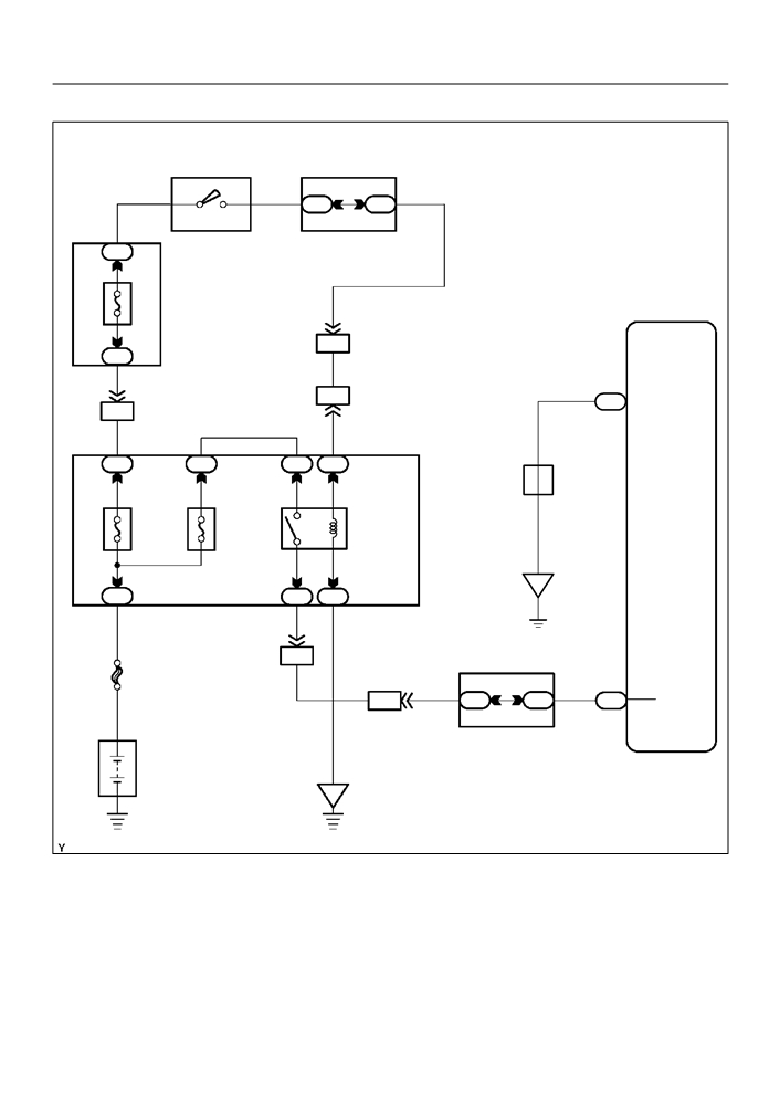
- SFI SYSTEM (April, 2003)
05DIT-01
FUEL PUMP CONTROL CIRCUIT
CIRCUIT DESCRIPTION
In the diagram below, when the engine is cranked, current flows from terminal ST2 of the ignition switch to
the starter relay coil and also current flows to terminal STA of the ECM (STA signal).
When the STA signal and NE signal are input to the ECM, Tr is turned ON, current flows to the coil of the
circuit opening relay, the relay switches on, power is supplied to the fuel pump and the fuel pump operates.
While the NE signal is generated (engine running), the ECM keeps Tr ON (circuit opening relay ON) and the
fuel pump also keeps operating.
Fuel Pump
EFI Relay
C/OPN Relay
ECM
EFI
FC
Tr
Ignition Switch
AM2
ST2
From
NE
Crankshaft Position Sensor
Clutch Start Switch*1
Park/Neutral position Switch*2
STA
ST Relay
Starter
Battery
*1: M/T
*2: A/T
A84734

05-279
DIAGNOSTICS
- SFI SYSTEM (April, 2003)
WIRING DIAGRAM
Instrument Panel J/B
ECM
From Terminal
5
1
10
B-W
1
2
G-R
FC
6 of Ignition
IL
IG
E6
Switch
C/OPEN
4
Relay
19
From Terminal
B
B-R
IG
ID
3 of EFI Relay
5
3
F10
4
Fuel
Pump
5
W-B
BH
A84936
INSPECTION PROCEDURE
Hand-held tester:
1
PERFORM ACTIVE TEST BY HAND-HELD TESTER(OPERATION OF CIRCUIT
OPENING RELAY)
(a) Connect the hand-held tester to the DLC3.
(b) Turn the ignition switch ON and push the hand-held tester main switch ON.
(c)
Select the item ”DIAGNOSIS / ENHANCED OBD II / ACTIVE TEST / FUEL PUMP / SPD”.
(d) Check the relay operation while operating it with the hand-held tester.
Standard: Operating noise can be heard from the relay.
OK Go to step 6
NG
2
INSPECT ECM POWER SOURCE CIRCUIT (See page 05-273)
NG REPAIR OR REPLACE POWER SOURCE
CIRCUIT
OK

05-280
DIAGNOSTICS
- SFI SYSTEM (April, 2003)
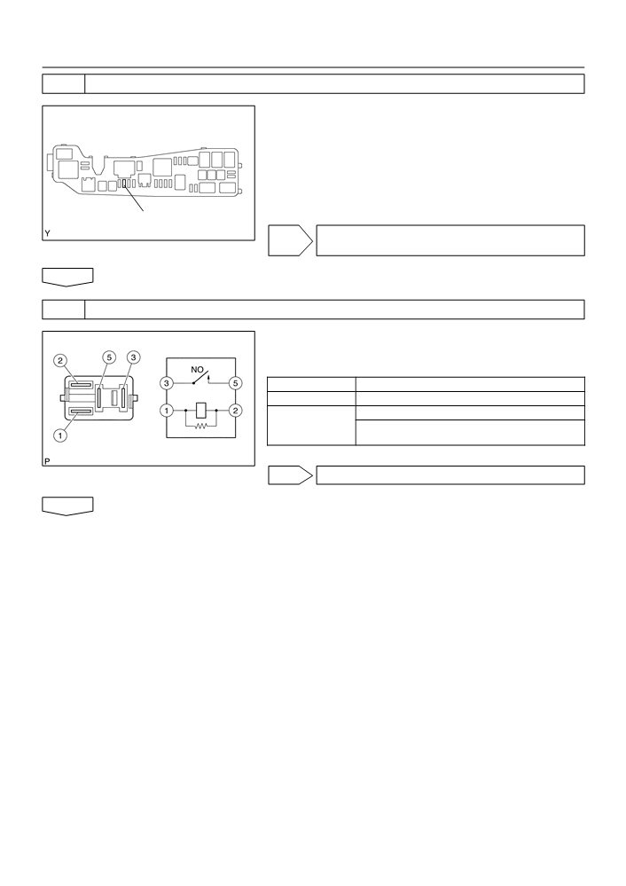
3
INSPECT CIRCUIT OPENING RELAY
(a) Remove the circuit opening relay from the instrument
panel J/B.
(b) Check for continuity in the circuit opening relay.
Standard:
Tester Connection
Specified Condition
1 - 2
Continuity
No continuity
3 - 5
Continuity
(Apply battery voltage to terminals 1 and 2)
E34090
(c)
Reinstall the circuit opening relay.
NG REPLACE CIRCUIT OPENING RELAY
OK
4
INSPECT ECM(FC VOLTAGE)
(a) Turn the ignition switch ON.
(b) Measure the voltage between the terminals of the E3 and
E3
E6
E6 ECM connectors.
Standard:
Tester Connection
Specified Condition
FC (E6-10) - E01 (E3-7)
9 to 14 V
E01 (-)
FC (+)
OK REPLACE ECM (See page 10-11)
ECM Connector
A18294
NG

05-281
DIAGNOSTICS
- SFI SYSTEM (April, 2003)
5
CHECK HARNESS AND CONNECTOR(EFI RELAY - CIRCUIT OPENING RELAY)
Engine Room R/B
(a) Remove the EFI relay from the engine room R/B.
(b) Remove the circuit opening relay from the instrument
panel J/B.
(c)
Check the resistance between the wire harness side con-
nectors.
Standard (Check for open):
EFI Relay
Tester Connection
Specified Condition
EFI relay (1) - Circuit opening relay (1)
Below 1 W
A65750
EFI relay (3) - Circuit opening relay (5)
Standard (Check for short):
Instrument Panel J/B:
Tester Connection
Specified Condition
EFI relay (1) or Circuit opening relay (1) - Body ground
10 kW or higher
EFI relay (3) or Circuit opening relay (5) - Body ground
(d) Reinstall the circuit opening relay.
(e) Reinstall the EFI relay.
Circuit Opening
Relay
A85429
NG REPAIR OR REPLACE HARNESS OR
CONNECTOR
OK
REPLACE ECM (See page 10-11)
6
INSPECT FUEL PUMP (See page 11-7)
NG REPAIR OR REPLACE FUEL PUMP
(See page 11-16)
OK