Toyota Corolla (2004+). Manual - part 49

05-642
DIAGNOSTICS
- COMBINATION METER
I30037

05-643
DIAGNOSTICS
- COMBINATION METER
18
28
2
BEAM-
13
17
DOOR
20
14
I/F I/F
6
TURN L
24
TURN R
8
I/F
25
30
I/F
5
9
I/F
4
26
CPU
I/F
19
LCD
OUTSIDE TEMP
D-BELT
1
LCD
I/F
ODO/TRIP
7
SPEED
22
FUEL WRN
TACHO
11
I/F
FUEL
12
I/F
TEMP
16
I/F
BUZZER
10
CHG
31
32
CHK E/G
33
O/D OFF
3
36
BRAKE
35
WASHER LEVEL (Canada)
34
37
ABS
OIL P
21
39
AIR BAG
CRUISE
23
I32739

05-644
DIAGNOSTICS
- COMBINATION METER
Terminal No.
Wire harness side
1
Ground (Signal Ground)
C9
2
Ground (Power Ground)
3
ECM
4
GAUGE Fuse
5
DOME Fuse
6
Front Passenger Seat Belt Warning Indicator
7
Fuel sender gauge
8
ECM
9
Skid Control ECU (w/ ABS), Vehicle Speed Control Sensor (w/o ABS)
10
Cruise Control ECU, ECM
11
Buckle Switch RH
12
Buckle Switch LH
13
Ground
14
HEAD RH UPR Fuse
15
-
16
Unlock Warning Switch
17
Driver Side Courtesy Switch
18
Tail Relay (USA), Combination Switch (Canada)
19
ECM
20
Except Driver Side Courtesy Switch
21
Engine Oil Pressure Switch
22
Fuel sender gauge
23
Cruise Control ECU
24
Turn Signal Flasher
25
Turn Signal Flasher
26
Ambient Temperature Sensor
28
Rheostat
30
Ambient Temperature Sensor
31
Alternator
32
GAUGE Fuse
33
ECM
34
Washer Level Sensor (Canada)
35
Brake Fluid Level Warning Switch
36
Skid Control ECU with Actuator (w/ ABS), Ground (w/o ABS)
37
Skid Control ECU with Actuator (w/ ABS), Ground (w/o ABS)
38
-
39
Airbag Sensor Assembly
40
-

05-666
DIAGNOSTICS
- COMBINATION METER
057T5-02
MALFUNCTION IN CLOCK
WIRING DIAGRAM
Clock
TAIL Relay (USA)
3
G
Combination SW (Canada)
RH J/B
11
18
2
3A
3A
W-B
W-B
10
5
4
3A
3A
GR
1
GR
Instrument Panel J/B
8
CIG
6
IF
IF
I10 Ignition SW
AM1
1
12
1
3
IB
IF
W
W
L-R
AM1
ACC
Center J/B
7
4
20
16
IC
IL
4C
4C
L-W
L-W
L-W
Engine Room J/B, R/B
A
J7
DOME
J/C
2
1
1
1
ALT
1
FL MAIN
2
1
1C
1A
B
Battery
IG
I32382
INSPECTION PROCEDURE
1
INSPECT FUSE
(a) Check the continuity in CIG fuse.
(b) Check the continuity in DOME fuse.
NG REPLACE FUSE
OK

05-667
DIAGNOSTICS
- COMBINATION METER
2
INSPECT HARNESS OR CONNECTOR
(a) Check voltage.
(1)
Remove the clock assy with connector still con-
nected.
(2)
Measure voltage between terminal 1 (+B) of clock
assy connector and body ground.
Standard voltage: 10 - 14 V
(3)
Turn the ignition switch to ACC.
+B E ILL ACC
(4)
Measure voltage between terminal 4 (ACC) of clock
I32727
assy connector and body ground.
Standard voltage: 10 - 14 V
(b) Check continuity.
(1)
Check continuity Between terminal 2 (E) of clock
assy connector and body ground.
OK: Continuity exists
NG REPAIR OR REPLACE HARNESS OR
CONNECTOR
OK
REPLACE CLOCK ASSY

05-655
DIAGNOSTICS
- COMBINATION METER
057KJ-02
MALFUNCTION IN FUEL RECEIVER GAUGE
WIRING DIAGRAM
F10
Combination Meter
Fuel Pump
Fuel Sender
22
13
BR
BR
ID2
C9
FUEL
2
3
EARTH
7
5
Y
Y
C9
FUEL
ID2
I32726
INSPECTION PROCEDERE
1
INSPECT FUEL SENDER GAGE ASSY
(a) Disconnect the connector fuel sender gauge.
(b) Check the float position between E and F and measure
the resistance between terminals 2 and 3 of the connec-
tor. Check that the resistance value changes continuous-
ly.
3
2
1
Standard:
Float level
Float position mm (in.)
Resistance (W)
F
64.5
(2.53)
3 (0.12)
15.0
1
e-3-1-B
E51362
1/2
11.6
(0.45)
3 (0.12)
54.7
3
E
52.7
(2.07)
3 (0.12)
107.0
1
F
12mm
1/2
(0 in.)
NG REPLACE FUEL SENDER GAGE ASSY
E
I32082
OK

05-656
DIAGNOSTICS
- COMBINATION METER
2
CHECK HARNESS AND CONNECTOR(BETWEEN FUEL SENDER GAGE AND
COMBINATION METER ASSY)
NG REPAIR OR REPLACE HARNESS OR
CONNECTOR
OK
CHECK AND REPLACE COMBINATION METER ASSY

05-650
DIAGNOSTICS
- COMBINATION METER
057KG-04
MALFUNCTION IN SPEEDOMETER
WIRING DIAGRAM
Vehicle Speed Sensor
Combination Meter
3
4
9
(*1)
(*1)
SP1
V1
II2
C9
SP IN
W-G
W-G
W-G
Skid Control ECU
with Actuator
17
14
(*2)
(*2)
SP1
S1
IA6
W-G
W-G
*1: w/o ABS
*2: w/ ABS
I32764
INSPECTION PROCEDURE
1
CHECK COMBINATION METER ASSY
(a) Remove the combination meter assy with connector still
connected.
(b) Check voltage.
(1)
Jack up either of the front wheels.
(2)
Shift the shift lever to neutral.
(3)
Turn the ignition switch to ON.
(4)
Measure the voltage between terminals C9-9 of
SP IN
combination meter assy and body ground when
I30040
front wheel is turning slowly.
Standard voltage:
Voltage is generated intermittently.
10 - 14V
0
Turn the wheel

05-651
DIAGNOSTICS
-
COMBINATION METER
Result:
A
B
C
OK
NG (w/ ABS)
NG (w/o ABS)
B
Go to step 2
C Go to step 3
A
CHECK AND REPLACE COMBINATION METER ASSY
2
CHECK OBD II SCAN TOOL OR HAND-HELD TESTER
(a) Check output value of skid control ECU.
(1)
Connect the hand-held tester to DLC3.
(2)
Turn the ignition switch to ON and push the hand-held tester main switch ON.
(3)
Select the DATA LIST mode on the hand-held tester.
(4)
Check that there is no difference between the speed value output from the speed sensor dis-
played by the hand-held tester and the speed value displayed by the speedometer when driving
the vehicle.
OK: There is almost no difference from the displayed speed value.
NG GO TO BRAKE SYSTEM
OK
REPAIR OR REPLACE HARNESS OR CONNECTOR
05-652
DIAGNOSTICS
- COMBINATION METER
3
INSPECT SPEEDOMETER SENSOR
(a) Check voltage.
(1)
Shift the shift lever to neutral.
(2)
Jack up either of the front wheel.
(3)
Turn the ignition switch to ON.
(4)
Measure voltage between terminals 3 and 2 of
speed sensor when the front wheel is turning slowly.
Standard voltage:
Voltage is generated intermittently.
I31248
10 - 14V
0
Turn the wheel
NG CHECK AND REPLACE SPEEDOMETER
SENSOR
OK
REPAIR OR REPLACE HARNESS OR CONNECTOR

05-653
DIAGNOSTICS
- COMBINATION METER
057KH-02
MALFUNCTION IN TACHOMETER
WIRING DIAGRAM
ECM
Combination Meter
5
19
TACH
E6
C9
TACHO
B
I32725
INSPECTION PROCEDURE
1
READ VALUE OF HAND-HELD TESTER
(a) Check output value of ECM.
(1)
Connect the hand-held tester to DLC3.
(2)
Turn the ignition switch to ON and push the hand-held tester main switch ON.
(3)
Select the DATA LIST mode on the hand-held tester.
Mesurement Item / Range
Item
Condition
Specified Condition
(Display)
Engine Speed /
ENGINE SPD
With Engine Idling
650 - 750rpm
Min.: 0 rpm, Max.: 16,383rpm
NG GO TO ENGINE CONTROL SYSTEM
OK

05-654
DIAGNOSTICS
- COMBINATION METER
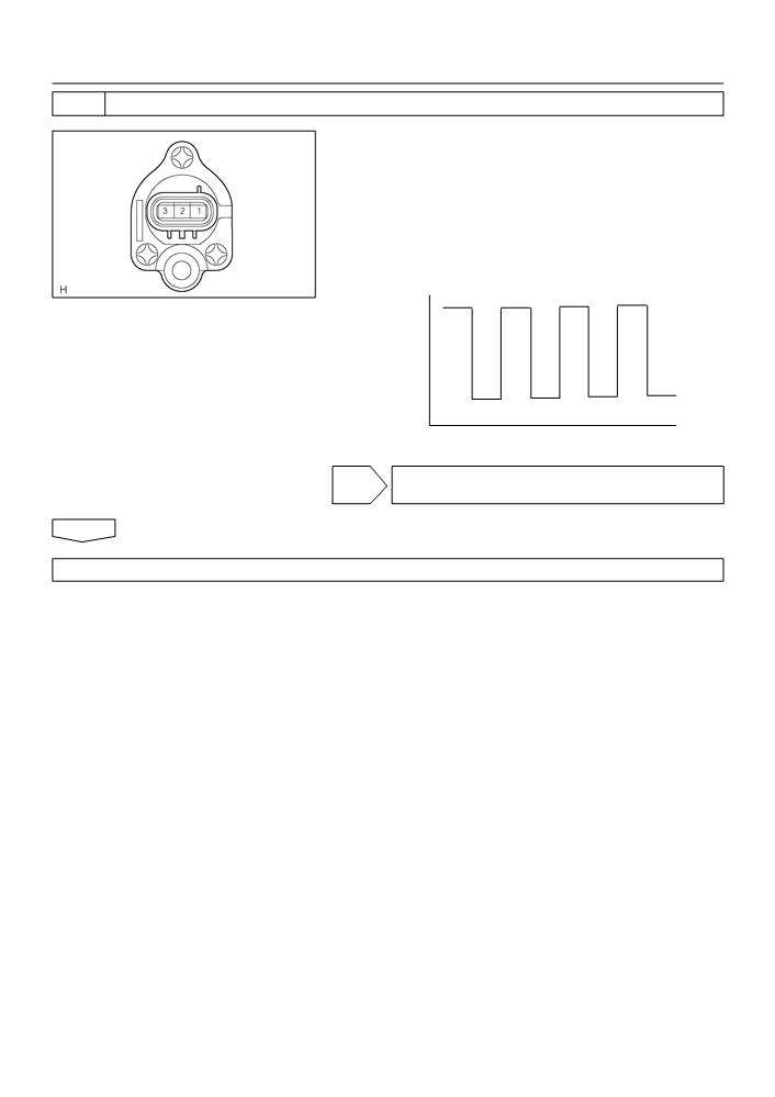
2
INSPECT COMBINATION METER ASSY
(REFERENCE) INSPECTION USING OSCILLOSCOPE
(a) Check the input signal waveform.
(1)
Remove the combination meter assy with connec-
tors still connected.
(2)
Connect the oscilloscope to the terminals C9-19 of
combination meter assy and body ground.
(3)
Start engine.
TACHO
(4)
Check the signal waveform.
I30040
Item
Contents
Tool setting
10 V/ DIV, 20 ms/ DV
Vehicle condition
Engine idle speed
E50835
OK CHECK AND REPLACE COMBINATION METER
ASSY
NG
3
CHECK HARNESS AND CONNECTOR(BETWEEN ECM AND COMBINATION
METER ASSY)
(a) Remove the combination meter.
(b) Check the continuity between terminals 5 (TACH) of ECM and C9-19 of combination meter connector.
Standard: There is continuity.
NG REPAIR OR REPLACE HARNESS OR
CONNECTOR
OK
CHECK AND REPLACE ECM

05-657
DIAGNOSTICS
- COMBINATION METER
057KI-02
MALFUNCTION IN WATER TEMPERATURE RECEIVER GAUGE
WIRING DIAGRAM
ECM
Combination Meter
14
8
THWO
E5
C9
TEMP
Y-R
I32725
INSPECTION PROCEDURE
1
READ VALUE OF HAND-HELD TESTER
(a) Check output value of ECM.
(1)
Connect the hand-held tester to DLC3.
(2)
Turn the ignition switch to ON and push the hand-held tester main switch ON.
(3)
Select the DATA LIST mode on the hand-held tester.
Mesurement Item /Range
Item
Condition
Specified Condition
(Display)
Coolant Temperature /
COOLANT TEMP
After Warming Up
80 - 95FC (176 - 203FF)
Min.: -40FC, Max.: 140FC
NG GO TO ENGINE CONTROL SYSTEM
OK

05-658
DIAGNOSTICS
- COMBINATION METER
2
INSPECT COMBINATION METER ASSY
(REFERENCE) INSPECTION USING OSCILLOSCOPE
(a) Check the input signal waveform.
(1)
Remove the combination meter with connectors still
connected.
(2)
Connect the oscilloscope to the terminals C9-8 of
combination meter assy and body ground.
(3)
Start engine.
TEMP
(4)
Check the signal waveform.
I32114
Item
Contents
Tool setting
5 V/ DIV, 100 ms/ DV
Vehicle condition
Ignition switch ON
I32122
OK CHECK AND REPLACE COMBINATION METER
ASSY
NG
3
CHECK HARNESS AND CONNECTOR(BETWEEN ECM AND COMBINATION
METER ASSY)
(a) Remove the combination meter.
(b) Check the continuity between terminals 14 (THWO) of ECM and C9-8 of combination meter connector.
Standard: There is continuity.
NG REPAIR OR REPLACE HARNESS OR
CONNECTOR
OK
CHECK AND REPLACE ECM

05-661
DIAGNOSTICS
- COMBINATION METER
057T4-02
SEAT BELT WARNING LAMP FOR DRIVER’S SEAT DOES NOT
OPERATE
WIRING DIAGRAM
B6
Buckle SW LH
Airbag Sensor Assy
Seat Position Sensor
Combination Meter
11
2
LBE+
A12
LBE+
G
1
12
3
3
4
L
IG1
C9
D-BELT SW
LSP+
A12
LSP+
G-Y
G-Y
G-W
4
1
LSP-
A12
5
LSP-
LBE-
R-B
W-B
J7
RH J/B
J/C
11
15
2
A
3A
3A
IG1
W-B
W-B
IG
I32384
INSPECTION PROCEDURE
1
CHECK COMBINATION METER ASSY
(a) Ground terminal C9-12 on the combination meter side.
(b) Check that the warning lightlights up.
OK: Warning light lights up.
D BELT SW
NG CHECK AND REPLACE COMBINATION METER
I30040
ASSY
OK