Toyota Corolla (2004+). Manual - part 48

DIAGNOSTICS
-
ELECTRONIC CONTROLLED AUTOMATIC
05-379
TRANSAXLE [ECT] (April, 2003)
05DU3-01
DTC
P0705
TRANSMISSION RANGE SENSOR CIRCUIT
MALFUNCTION (PRNDL INPUT)
DTC
P0850
PARK/NEUTRAL SWITCH INPUT CIRCUIT
CIRCUIT DESCRIPTION
The park/neutral position switch detects the shift lever position and sends signals to the ECM.
DTC No.
DTC Detecting Condition
Trouble Area
2 or more switches are ON simultaneously for P, R, N, 2 and L
P0705
positions (2-trip detection logic)
Park/neutral position switch remains ON (P, N position) during
F Open or short in park/neutral position switch circuit
driving under conditions (a) and (b) for 30 sec. (2-trip detection
F Park/neutral position switch
P0850
logic)
F ECM
(a) Vehicle speed: 70 km/h (44 mph) or more
(b) Engine speed: 1,500 - 2,500 rpm
MONITOR DESCRIPTION
The park/neutral position switch detects the gearshift position and sends a signal to the ECM.
For security, the park/neutral position switch detects the gearshift position so that engine can be started only
when the vehicle is in P or N shift position.
When the park/neutral position switch sends more than one signal at a time from switch positions P, R, N,
2, or L the ECM interprets this as a fault in the switch. The ECM will turn on the MIL.
MONITOR STRATEGY
P0705
Shift lever position select switch/Verify switch
Related DTCs
P0705
input
Required sensors/Components
Park/neutral position switch
Frequency of operation
Continuous
Duration
0.5 sec.
MIL operation
2 driving cycles
Sequence of operation
None
P0850
Related DTCs
P0850
Park/neutral position switch/Verify switch cycling
Required sensors/Components
Park/neutral position switch
Frequency of operation
Continuous
Duration
30 sec.
MIL operation
2 driving cycles
Sequence of operation
None

05-380
DIAGNOSTICS
- ELECTRONIC CONTROLLED AUTOMATIC
TRANSAXLE [ECT] (April, 2003)
TYPICAL ENABLING CONDITION
P0705
Specification
Item
Minimum
Maximum
The monitor will run whenever the follow-
See page 05-369
ing DTCs are not present.
The typical enabling condition is not avail-
-
able.
P0805
Specification
Item
Minimum
Maximum
The monitor will run whenever the follow-
See page 05-369
ing DTCs are not present.
Vehicle speed
70 km/h (43 mph) or more
-
Engine speed
1,500 rpm or more
2,700 rpm or less
Intake air amount per revolution
0.43 g/rev. or more
-
TYPICAL MALFUNCTION THRESHOLDS
P0705
Detection criteria
Threshold
Number of the following signal input at the same time.
2 or more
Park/neutral position switch
ON
L shift position switch
ON
2 shift position switch
ON
R shift position switch
ON
P0850
Detection criteria
Threshold
PNP signal
ON
COMPONENT OPERATING RANGE
Parameter
Standard value
Park/neutral position switch
The park/neutral position switch sends only one signal to the ECM.

DIAGNOSTICS
- ELECTRONIC CONTROLLED AUTOMATIC
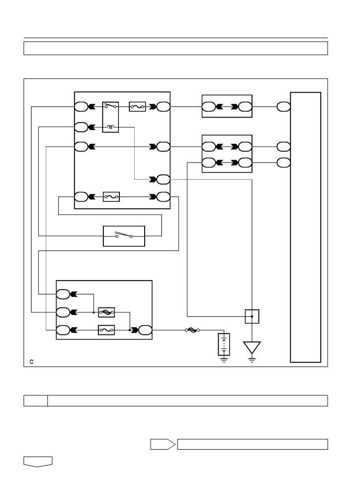
05-381
TRANSAXLE [ECT] (April, 2003)
WIRING DIAGRAM
J/C
ECM
A
G
R
To
J2
J2
ST Relay
B
G
G
9
A2
B
J2
J2
E4
STA
Park/Neutral Position SW
A
E
8
R
R
J2
J3
E4
NSW
6
9
2
8
LG-B
LG-B
II1
E5
L
LL
8
5
9
LG
LG
II1
E5
2
2L 4
3
RB
13
R-B
R-B
II2
RL 2
To
11
1
Combination Mater
RH J/B
E5
R
5
14
20
22
R-W
R-W
R-W
R-W
II2
3B
3B
B
B
12
R J4 J/C
R
B-Y
II2
R-B
R-B
4
2
Instrument Panel J/B
ST2
IG1
I10
9
10
Ignition SW
IK
IK
AM2
AM1
2
GAUGE
R-W
5
1
IG
Engine Room J/B and R/B
B-Y
IG1 Relay
1
ALT
1
1
W W
W
1A
1D
IA
1
2
W
5
3
2
4
B
MAIN
IF
IF
B-R
1
2
1
12
AM1
1
1
2
1
IF
IB
W
1C
2
IA4
6
AM2
3
W-B
IM
IM
FL MAIN
B
A
B-R
J6
J/C
W
W-B
Battery
IE
G27785

05-382
DIAGNOSTICS
- ELECTRONIC CONTROLLED AUTOMATIC
TRANSAXLE [ECT] (April, 2003)
INSPECTION PROCEDURE
1
INSPECT PARK/NEUTRAL POSITION SWITCH ASSY
(a) Disconnect the park/neutral position switch connector.
Switch Side:
(Connector Front View):
(b) Measure resistance according to the value(s) in the table
below when the shift lever is moved to each position.
Standard:
Shift Position
Tester Connection
Specified Condition
P
Below 1 W
1 - 3 and 6 - 9
Except P
10 kW or higher
R
Below 1 W
A2
G27076
2- 3
Except R
10 kW or higher
N
Below 1 W
3 - 5 and 6 - 9
Except N
10 kW or higher
D
Below 1 W
3 - 7
Except D
10 kW or higher
2
Below 1 W
3 - 4
Except 2
10 kW or higher
L
Below 1 W
3- 8
Except L
10 kW or higher
NG REPLACE PARK/NEUTRAL POSITION SWITCH
ASSY (See page 40-3)
OK

DIAGNOSTICS
- ELECTRONIC CONTROLLED AUTOMATIC
05-383
TRANSAXLE [ECT] (April, 2003)
2
CHECK HARNESS AND CONNECTOR(PARK/NEUTRAL POSITION SWITCH -
ECM)
(a) Connect the the park/neutral position switch connector.
(b) Turn the ignition switch to the ON position, and measure
E3
E4
E5
E6
the voltage according to the value(s) in the table below
when the shift lever is moved to each position.
ECM:
NSW(+)
L(+)
R(+)
2(+)
C96070
Standard:
Shift Position
Tester Connection
Specified condition
P and N
Below 1 V
E4
- 8
(NSW) - Body ground
Except P and N
10 to 14 V
R
10 to 14 V*
E5 - 11 (R) - Body ground
Except R
Below 1 V
2
10 to 14 V
E5 - 9 (2) - Body ground
Except 2
Below 1 V
L
10 to 14 V
E5
- 8
(L) - Body ground
Except L
Below 1 V
HINT:
*: The voltage will drop slightly due to lighting up of the back up
light.
NG REPAIR OR REPLACE HARNESS OR
CONNECTOR (See page 01-30)
OK
REPLACE ECM (See page 10-11)

05-346
DIAGNOSTICS
- ELECTRONIC CONTROLLED AUTOMATIC
TRANSAXLE [ECT] (April, 2003)
0527H-17
HOW TO PROCEED WITH TROUBLESHOOTING
The hand-held tester can be used at step 3, 4, 6, 9.
1
Vehicle Brought to Workshop
2
Customer Problem Analysis (See page
05-349)
3
Connect the OBD II scan tool or hand-held tester to DLC3
4
Check and Clear DTC and Freeze Frame Data (See page
05-353)
5
Visual Inspection
6
Setting the Check Mode Diagnosis (See page
05-354)
7
Problem Symptom Confirmation (See page
05-356)
Symptom does not occur: Go to step 8
Symptom occur: Go to step 9
8
Symptom Simulation (See page
01-20)
9
DTC Check (See page 05-353)
DTC is not output: Go to step 10
DTC is output: Go to step 18

DIAGNOSTICS
-
ELECTRONIC CONTROLLED AUTOMATIC
05-347
TRANSAXLE [ECT] (April, 2003)
10
Basic Inspection (See page
40-2, 40-6 and 40-44)
NG Go to step 20
OK
11
Mechanical System Test (See page
05-358)
NG Go to step 17
OK
12
Hydraulic Test (See page
05-360)
NG Go to step 17
OK
13
Manual Shifting Test (See page
05-361)
NG Go to step 15
OK
14
Problem Symptoms Table Chapter 1 (See page
05-374)
NG Go to step 19
OK
15
Problem Symptoms Table Chapter 2 (See page
05-374)
NG Go to step 17
OK
16
Problem Symptoms Table Chapter 3 (See page
05-374)
NG
17
Part Inspection
Go to step 20
18
DTC Chart (See page 05-372)

05-348
DIAGNOSTICS
- ELECTRONIC CONTROLLED AUTOMATIC
TRANSAXLE [ECT] (April, 2003)
19
Circuit Inspection
20
Identification of Problem
21
Repair
22
Confirmation Test
End
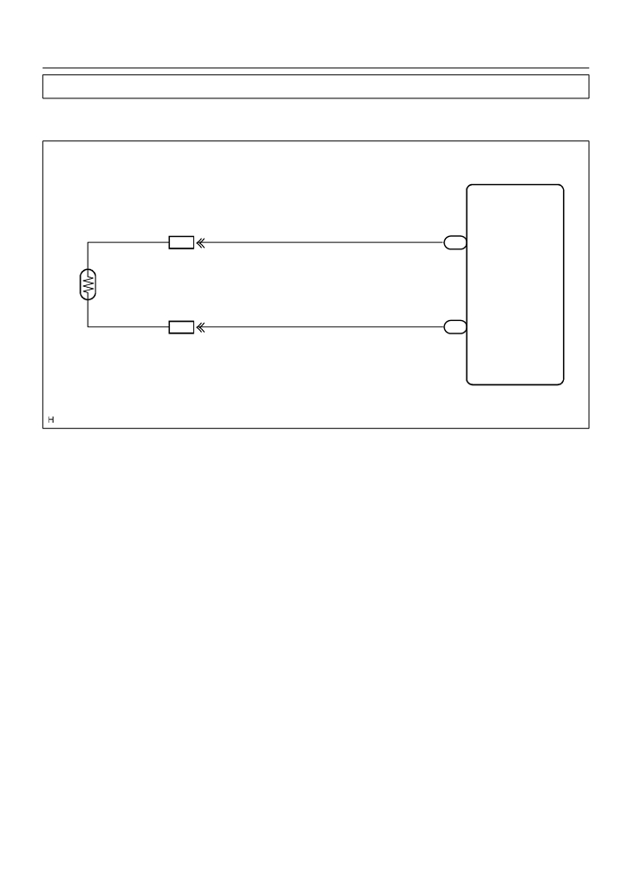
05-668
DIAGNOSTICS
- COMBINATION METER
057KO-04
THE AMBIENT TEMPERATURE DOES NOT DISPLAY
WIRING DIAGRAM
Combination Meter
3
26
IA6
C9
OUT SIDE TEMP+
B
B
1
A7
Ambient
Temperature
2
Sensor
10
30
IA6
C9
OUT SIDE TEMP-
B-L
B-L
I37764

05-669
DIAGNOSTICS
- COMBINATION METER
INSPECTION PROCEDURE
1
INSPECT OUTER AMBIENT TEMPERATURE SENSOR
(a) Remove cooler (ambient temp. sensor) thermistor.
(b) Measure resistance between terminals 1 and 2 of cooler
(ambient temp. sensor) thermistor connector at each tem-
perature.
Resistance:
1
2
at 0 FC (0 FF) : 9.097 - 9.701 k W
at 25 FC (77 FF) : 2.725 - 2.865 k W
HINT:
I30487
As the temperature increases, the resistance decreases.
Resistance:
Resistance (kW)
Temperature (FC)
I30156
NG REPLACE OUTER AMBIENT TEMPERATURE
SENSOR
OK
2
CHECK HARNESS AND CONNECTOR
NG REPAIR OR REPLACE HARNESS OR
CONNECTOR
OK
CHECK AND REPLACE COMBINATION METER ASSY

05-639
DIAGNOSTICS
- COMBINATION METER
057KB-02
CUSTOMER PROBLEM ANALYSIS CHECK
COMBINATION METER Check Sheet
Inspector’s name:
Registration No.
Customer’s Name
Registration Year
Frame No.
Date of Vehicle
Km
Odometer Reading
Brought in
Mile
Date Problem First Occurred
How Often Problem Occurs
Continuous
Intermittent (
Times a day)
Weather
Fine
Cloudy
Snowy
Other
Temperature
Approx.
Malfunction in speedometer
Malfunction in tachometer
Malfunction in fuel receiver gauge
Malfunction in water temperature receiver
gauge
Key unlock warning buzzer does not sound
Light auto-turn off warning buzzer does not sound
Malfunction in driver’s seat belt warning buzzer
All buzzers do not sound
I30045
05-648
DIAGNOSTICS
- COMBINATION METER
057T2-02
ENTIRE COMBINATION METER DOES NOT OPERATE
WIRING DIAGRAM
Combination Meter
Instrument Panel J/B
RH J/B
1
IG1 Relay GAUGE
2
22
16
4
IA
IG
3B
3B
C9
IG1
W
5
3
R-W
R-W
2
IF
B-Y
1
2
Center J/B
7
4
20
19
5
IC
IL
4C
4C
C9
+B
L-W
L-W
L-W
21
18
2
4B
4B
C9
POWER
W-B
EARTH
4
IF
W-B
12
AM1
1
IF
IB
W
I10 Ignition Switch
W-B
2
1
IG1
AM1
W
Engine Room J/B, R/B
1
1C
1
ALT
A
2
1
1D
A
J6
DOME
1
J/C
FL MAIN
2
1
1
1A
B
Battery
IE
I32767
INSPECTION PROCEDERE
1
CHECK FUSE
(a) Check that continuity exists of DOME fuse.
(b) Check that continuity exists of GAUGE fuse.
(c)
Check that continuity exists of AM1 fuse.
NG REPLACE FUSE
OK

05-649
DIAGNOSTICS
- COMBINATION METER
2
INSPECT COMBINATION METER ASSY
(a) Check continuity.
(1)
Disconnect the ”C9” connector from combination
meter assy.
(2)
Check continuity between terminal C9-2 of com-
bination meter assy connector and body ground.
OK: Continuity exists
POWER
EARTH
I32115
(b) Check voltage.
(1)
Disconnect the ”C9” connector from combination
meter assy.
(2)
Measure voltage between terminal C9-5 of com-
bination meter assy connector and body ground.
Voltage: 10 - 14 V
(3)
Turn the ignition switch to ON.
(4)
Measure voltage between terminal C9-4 of com-
IG1
+B
I32115
bination meter assy connector and body ground.
Voltage: 10 - 14 V
NG REPAIR OR REPLACE HARNESS OR
CONNECTOR
OK
CHECK AND REPLACE COMBINATION METER ASSY

05-640
DIAGNOSTICS
- COMBINATION METER
057KC-02
LOCATION
Combination Meter
Brake Fluid Level Warning Switch
Fuel Sender Gauge
Rear Door Courtesy
Switch
Front Door Courtesy Switch
Engine Room J/B, R/B
F DOME Fuse
I32723

05-641
DIAGNOSTICS
- COMBINATION METER
ECM
Passenger Seat Belt Warning
Light Assembly
Key Unlock Warning
Switch
RH J/B
Transmission Control Switch
Center J/B
Parking Brake Switch
Instrument Panel J/B
F GAUGE Fuse
Front Seat Belt Inner Belt
F AM1 Fuse
(Passenger’s)
Separate Type Front Seat
Cushion Pad
Front Seat Belt Inner
Belt (Driver’s)
I32724