Toyota Corolla (2004+). Manual - part 33

42-14
CLUTCH
- CLUTCH RELEASE CYLINDER ASSY (MTM)
CLUTCH RELEASE CYLINDER ASSY (MTM)
4203Q-01
COMPONENTS
5.0 (51, 44 in. lbf)
15.2 (155, 11)
Flexible Hose Tube
Flexible Hose Tube
11.8 (120, 9)
Bracket
Bleeder Plug
8.4 (85, 74 in. lbf)
Release Cylinder Bleeder Plug Cap
Release Cylinder Body
Piston
Push Rod
F Spring
Boot
Nm (kgfcm, ftlbf)
: Specified torque
F Non-reusable part
Lithium soap base glycol grease
D11545

42-15
CLUTCH
- CLUTCH RELEASE CYLINDER ASSY (MTM)
4203R-01
OVERHAUL
1.
DRAIN CLUTCH FLUID
2.
DISCONNECT CLUTCH RELEASE CYLINDER TO
FLEXIBLE HOSE TUBE
(a) Using SST, disconnect the flexible hose tube.
SST
09023-00100
HINT:
Use a container to catch the fluid.
SST
D26809
3.
REMOVE CLUTCH RELEASE CYLINDER ASSY
(a) Remove the 3 bolts, clutch release cylinder assy and
clutch line bracket.
D26810
4.
REMOVE CLUTCH RELEASE CYLINDER KIT
(a) Remove the boot from the cylinder body.
(b) Remove the push rod from the cylinder body.
(c)
Remove the piston from the cylinder body.
NOTICE:
Be careful not to damage the inside of the cylinder body.
(d) Remove the spring from the cylinder body.
(e) Remove the bleeder plug cap from the bleeder plug.
5.
REMOVE RELEASE CYLINDER BLEEDER PLUG
6.
INSTALL RELEASE CYLINDER BLEEDER PLUG
Torque: 8.4 N m (85 kgf cm, 74 in. lbf)

42-16
CLUTCH
- CLUTCH RELEASE CYLINDER ASSY (MTM)
7.
INSTALL CLUTCH RELEASE CYLINDER KIT
(a) Install the bleeder plug cap to the bleeder plug.
(b) Install a new spring to the cylinder body.
(c)
Coat parts with lithium soap base glycol grease, as shown
in the illustration.
(d) Install the piston to the cylinder body.
NOTICE:
Be careful not to damage the inside of the cylinder body.
(e) Install the push rod to the cylinder body.
(f)
Install the boot to the cylinder body.
CL0672
8.
INSTALL CLUTCH RELEASE CYLINDER ASSY
(a) Install the clutch release cylinder and clutch line bracket
with the 2 bolts.
Torque: 11.8 N m (120 kgf cm, 9 ft lbf)
(b) Install the flexible hose tube with the bolt.
Torque: 5.0 N m (51 kgf cm, 44 in. lbf)
D26810
9.
CONNECT CLUTCH RELEASE CYLINDER TO
FLEXIBLE HOSE TUBE
(a) Using SST, connect the flexible hose tube.
SST
09023-00100
Torque: 15.2 N m (155 kgf cm, 11 ft lbf)
SST
D26809
10. BLEED CLUTCH PIPE LINE
(a) Fill the brake reservoir tank with brake fluid and bleed clutch system.
Torque: 8.4 N m (85 kgf cm, 74 in. lbf)
11. CHECK CLUTCH FLUID LEAKAGE
42-23
CLUTCH
- CLUTCH START SWITCH ASSY (MTM)
42029-02
INSPECTION
1.
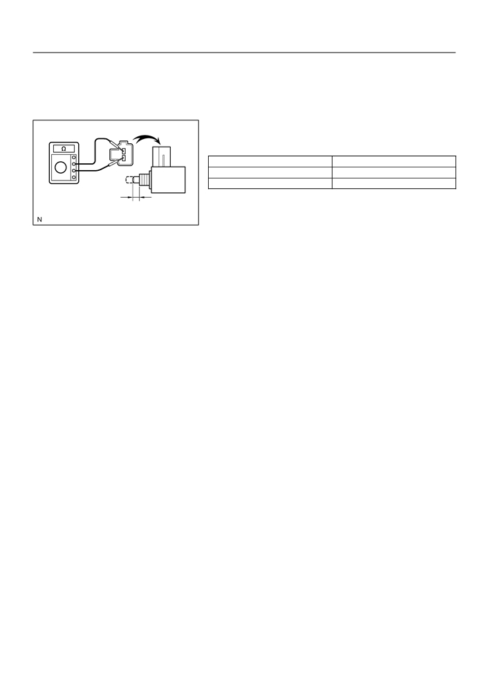
INSPECT CLUTCH START SWITCH ASSY
(a) Check the continuity between the terminals when the
switch is ON and OFF.
Switch position
Condition
ON (pushed)
Continuity
OFF (free)
No continuity
8.0
0.5 mm
(0.315
0.020 in.)
D11485

42-22
CLUTCH
- CLUTCH START SWITCH ASSY (MTM)
CLUTCH START SWITCH ASSY (MTM)
42028-02
ON-VEHICLE INSPECTION
1.
CHECK CLUTCH START SYSTEM
(a) Check that the engine does not start when the clutch ped-
al is released.
(b) Check that the engine starts when the clutch pedal is fully
depressed.
If necessary, replace the clutch start switch assy.
Clutch Start Switch
Assy
D26340
42-24
CLUTCH
- CLUTCH START SWITCH ASSY (MTM)
4203U-01
REPLACEMENT
1.
REMOVE CLUTCH START SWITCH ASSY
(a) Disconnect the clutch start switch assy connector.
(b) Remove the nut and clutch start switch assy from the clutch pedal support.
2.
INSTALL CLUTCH START SWITCH ASSY
(a) Install the clutch start switch assy with the nut.
Torque: 15.68 N m (160 kgf cm, 12 ft lbf)
(b) Connect the clutch start switch assy connector.
3.
INSPECT CLUTCH START SWITCH ASSY (See page 42-22)

42-17
CLUTCH
- CLUTCH UNIT (MTM)
CLUTCH UNIT (MTM)
4203S-01
COMPONENTS
Clutch Disc Assy
19.1 (195, 14)
Clutch Release
x6
Fork Sub-assy
Clutch Release
Bearing Assy
Release Bearing
Hub Clip
Flywheel Sub-assy
Clutch Cover Assy
Release Fork Support
36.8 (375, 27)
Clutch Release Fork Boot
Nm (kgfcm, ftlbf)
: Specified torque
Clutch spline grease
Release hub grease
D26321

42-18
CLUTCH
- CLUTCH UNIT (MTM)
4203T-01
OVERHAUL
1.
REMOVE MANUAL TRANSAXLE ASSY (See page 41-17)
2.
REMOVE CLUTCH RELEASE FORK SUB-ASSY
(a) Remove the clutch release fork with clutch release bear-
ing from the transaxle assy.
Q01056
3.
REMOVE CLUTCH RELEASE BEARING ASSY
(a) Remove the clutch release bearing assy from the clutch release fork.
4.
REMOVE RELEASE FORK SUPPORT
(a) Remove the release fork support from the transaxle assy.
5.
REMOVE RELEASE BEARING HUB CLIP
6.
REMOVE CLUTCH RELEASE FORK BOOT
7.
REMOVE CLUTCH COVER ASSY
(a) Align the matchmarks on the clutch cover assy with the
one on the flywheel sub-assy.
(b) Loosen each set bolt one turn at a time until spring tension
is released.
(c)
Remove the 6 bolts, and pull off the clutch cover assy.
NOTICE:
Do not drop the clutch disc assy.
C62955
Matchmarks
D25280
8.
REMOVE CLUTCH DISC ASSY
NOTICE:
Keep the lining part of the clutch disc assy, the pressure plate and surface of the flywheel sub-assy
away from oil and foreign attachment.
9.
INSPECT CLUTCH DISC ASSY
(a) Using vernier calipers, measure the rivet head depth.
Maximum rivet depth: 0.3 mm (0.012 in.)
If necessary, replace the clutch disc assy.
(b) Install the clutch disc assy to the transaxle assy.
NOTICE:
Take care not to insert the clutch disc assy in the wrong
direction.
C62956

42-19
CLUTCH
- CLUTCH UNIT (MTM)
(c)
Using a dial indicator, check the clutch disc assy runout.
Minimum runout: 0.8 mm (0.031 in.)
Transaxle
If necessary, replace the clutch disc assy.
Side
D26338
10. INSPECT CLUTCH COVER ASSY
B
(a) Using vernier calipers, inspect the diaphragm spring for
A
depth and width of wear.
Maximum:
A (Depth): 0.5 mm (0.020 in.)
B (Width): 6.0 mm (0.236 in.)
If necessary, replace clutch cover assy.
C57466
D25281
11. INSPECT FLYWHEEL SUB-ASSY
(a) Using a dial indicator, inspect the flywheel sub-assy run-
out.
Maximum runout: 0.1 mm (0.004 in.)
If necessary, replace the flywheel sub-assy.
C62958
12. INSPECT CLUTCH RELEASE BEARING ASSY
(a) Turn the release bearing by hand while applying force in
the axial direction.
HINT:
The bearing is permanently lubricated and requires no cleaning
or lubrication.
If necessary, replace the release bearing assy.
Q01060
13. INSTALL CLUTCH DISC ASSY
(a) Insert SST in the clutch disc assy, then insert them in the
flywheel sub-assy.
SST
09301-00210
Flywheel Side
NOTICE:
Take care not to insert clutch disc assy in the wrong direc-
tion.
SST
D26339

42-20
CLUTCH
- CLUTCH UNIT (MTM)
14. INSTALL CLUTCH COVER ASSY
7
1 (Temporally), 4
SST
(a) Align the matchmarks on the clutch cover assy and fly-
wheel sub-assy.
3
(b) Following the procedures shown in the illustration, tighten
the 6 bolts, in the order starting the bolt locating near the
6
knock pin on the top.
5
Torque: 19.1 N m (195 kgf cm, 14 ft lbf)
HINT:
Matchmarks
2
D26323
F
Following the order in the illustration, tighten the bolts at
a time evenly.
F
Move SST up and down, right and left lightly, after check-
ing that the disc is in the center, tighten the bolts.
15. INSPECT AND ADJUST CLUTCH COVER ASSY
(a) Using a dial indicator with roller instrument, check the dia-
SST
phragm spring tip alignment.
Maximum non-alignment: 0.5 mm (0.020 in.)
If alignment is not as specified, using SST, adjust the dia-
phragm spring tip alignment.
SST
09333-00013
D00205
16.
INSTALL RELEASE FORK SUPPORT
(a)
Install the release fork support to the transaxle assy.
Torque: 36.8 N m (375 kgf cm, 27 ft lbf)
17.
INSTALL RELEASE BEARING HUB CLIP
18. INSTALL CLUTCH RELEASE FORK SUB-ASSY
(a) Apply release hub grease to the release fork and release
bearing assy contact, release fork and push rod contact
and release fork pivot points.
Sealant:
Part No. 08887-01806, RELEASE HUB GREASE or
equivalent
(b) Install the release fork to the release bearing assy.
Release hub grease
D27398
19.
INSTALL CLUTCH RELEASE BEARING ASSY
(a)
Apply the clutch spline grease to the input shaft spline.
Sealant:
Part No. 08887-01706, CLUTCH SPLINE GREASE or equivalent
(b)
Install the bearing to the release fork, and then install them to the transaxle assy.
NOTICE:
After the installation, move the folk forward and backward to check that the release bearing slides
smoothly.
42-21
CLUTCH
-
CLUTCH UNIT (MTM)
20. INSTALL CLUTCH RELEASE FORK BOOT
21. INSTALL MANUAL TRANSAXLE ASSY (See page
41-17)

42-1
CLUTCH
- CLUTCH SYSTEM (MTM)
CLUTCH SYSTEM (MTM)
4203K-01
PROBLEM SYMPTOMS TABLE
HINT:
Use the table below to help you find the cause of the problem. The numbers indicate the priority of the likely
cause of the problem. Check each part in order. If necessary, replace these parts.
Symptom
Suspect Area
See page
5. Engine mounting (Loosen)
-
6. Clutch disc assy (Runout is excessive)
42-18
7. Clutch disc assy (Oily)
42-18
Clutch grabs/chatters
8. Clutch disc assy (Worn out)
42-18
9. Clutch disc torsion rubber (Damaged)
42-18
10.Clutch disc assy (Glazed)
42-18
42-18
11.Diaphragm spring (Out of tip alignment)
1. Clutch Line (Air in line)
-
Clutch pedal spongy
2. Master cylinder cup (Damaged)
42-10
3. Release cylinder rubber (Damaged)
42-15
1. Clutch release bearing assy (Worn, dirty, or damaged)
42-15
Clutch noisy
2. Clutch disc torsion rubber (Damaged)
42-18
1. Clutch pedal (Free play out of adjustment)
42-2
2. Clutch disc assy (Oily)
42-18
3. Clutch disc assy (Worn out)
42-18
Clutch slips
4. Diaphragm spring (Damaged)
42-18
5. Pressure plate (Distortion)
42-18
6. Flywheel sub-assy (Distortion)
-
1. Clutch pedal (Free play out of adjustment)
42-2
2. Clutch line (Air in line)
-
3. Master cylinder cup (Damaged)
42-10
4. Release cylinder cup (Damaged)
42-15
5. Clutch disc assy (Out of true)
42-18
Clutch does not disengage
6. Clutch disc assy (Runout of excessive)
42-18
7. Clutch disc assy (Lining broken)
42-18
8. Clutch disc assy (Dirty or burned)
42-18
9. Clutch disc assy (Oily)
42-18
10.Clutch disc assy (Lack of spline grease)
42-18

50-3
STEERING COLUMN
- STEERING
5000P-03
ON-VEHICLE INSPECTION
1.
CHECK STEERING WHEEL FREEPLAY
(a) Stop the vehicle and face the tires straight ahead.
(b) Rock the steering wheel gently up and down by your
hand, check the steering wheel freeplay.
Maximum freeplay: 30 mm (1.18 in.)
F42427
50-1
STEERING COLUMN
- STEERING
STEERING SYSTEM
5003T-01
PRECAUTION
1.
HANDLING PRECAUTIONS ON STEERING SYSTEM
(a) Care must be taken when replacing parts. Incorrect replacement may affect the performance of the
steering system and result in a driving hazard.
2.
HANDLING PRECAUTIONS ON SRS AIRBAG SYSTEM
(a) The vehicle is equipped with SRS (Supplemental Restraint System) such as the driver airbag and front
passenger airbag. Failure to carry out service operation in the correct sequence could cause the SRS
to unexpectedly deploy during servicing, possibly leading to a serious accident. Before servicing (in-
cluding removal or installation of parts, inspection or replacement), be sure to read the precautionary
notice for the supplemental restraint system (See page 60-1).

50-4
STEERING COLUMN
- STEERING
5002Q-02
REPAIR
1.
STEERING OFF CENTER REPAIR PROCEDURE
(a) Inspect steering wheel off center.
Steering Wheel
(1)
Apply masking tape on the top center of the steering
Masking Tape
wheel and steering column upper cover.
(2)
Driving the vehicle on a straight line for 100 meters
Steering Column
at a constant speed of 35 mph (56 km/h), and hold
Upper Cover
the steering wheel to maintain the course.
F16015
(3)
Draw a line on the masking tape as shown in the il-
Steering Column
Upper Cover
lustration.
Marked Line
Steering Wheel
Masking
Tape
F16016
(4)
Turn the steering wheel to its straight position.
Steering Column
HINT:
Upper Cover
Refer to the upper surface of the steering wheel, steering spoke
Marked Line
and SRS airbag line for the straight position.
Steering Wheel
(5)
Draw a new line on the masking tape or the steering
wheel as shown in the illustration.
(6)
Measure the distance between the 2 lines on the
masking tape of the steering wheel.
F16017