Toyota Corolla (2004+). Manual - part 31
41-83
MANUAL TRANSMISSION/TRANSAXLE
- OUTPUT SHAFT ASSY (C59)
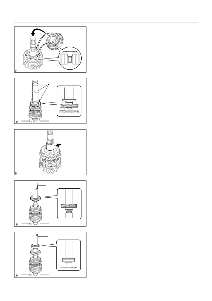
34. INSTALL 2ND GEAR
(a) Coat the 2nd gear with gear oil, install it to the output
shaft.
NOTICE:
Fit the synchronizer inner ring claws into the slots in the
transmission clutch hub No.1.
C95326
35. INSTALL 3RD DRIVEN GEAR
SST
(a) Using SST and a press, install the 3rd driven gear to the
output shaft.
SST
09309-36100 (09309-03610), 09608-00071,
09950-60010 (09951-00450)
C94310
36. INSTALL OUTPUT GEAR SPACER
(a) Install the output gear spacer to the output shaft.
C68005
37. INSTALL 4TH DRIVEN GEAR
SST
(a) Using SST and a press, install 4th driven gear to the out-
put shaft.
SST
09612-22011
C94311
38. INSTALL OUTPUT SHAFT REAR BEARING
SST
(a) Using SST and a press, install output shaft rear bearing
to the output shaft.
SST
09612-22011
C94312

41-84
MANUAL TRANSMISSION/TRANSAXLE
- OUTPUT SHAFT ASSY (C59)
39. INSPECT 2ND GEAR RADIAL CLEARANCE
(a) Using a dial indicator, measure the 2nd gear radial clear-
ance.
Standard clearance:
Bearing
Clearance: mm (in.)
KOYO made
0.015 - 0.058 (0.0006 - 0.0023)
NSK made
0.015 - 0.056 (0.0006 - 0.0022)
If the clearance is out of specification, replace the 2nd gear
C68254
needle roller bearing.
40. INSPECT 1ST GEAR RADIAL CLEARANCE
(a) Using a dial indicator, measure the 1st gear radial clear-
ance.
Standard clearance:
Bearing
Clearance: mm (in.)
KOYO made
0.015 - 0.058 (0.0006 - 0.0023)
NSK made
0.015 - 0.056 (0.0006 - 0.0022)
If the clearance is out of specification, replace the 1st gear
C68309
needle roller bearing.
41. INSPECT 2ND GEAR THRUST CLEARANCE
(a) Using a dial indicator, measure the 2nd gear thrust clear-
ance.
Standard clearance:
0.10 - 0.45 mm (0.0039 - 0.0177 in.)
C68312
42. INSPECT 1ST GEAR THRUST CLEARANCE
(a) Using a feeler gauge, measure the 1st gear thrust clear-
ance.
Standard clearance:
0.10 - 0.40 mm (0.0039 - 0.0157 in.)
C68252
41-17
MANUAL TRANSMISSION/TRANSAXLE
- MANUAL TRANSAXLE ASSY
4107D-02
REPLACEMENT
HINT:
COMPONENTS: See page 41-15
1.
PLACE FRONT WHEELS FACING STRAIGHT AHEAD
2.
REMOVE FRONT WHEELS
3.
REMOVE ENGINE UNDER COVER LH
4.
REMOVE ENGINE UNDER COVER RH
5.
REMOVE EXHAUST PIPE (See page 15-2)
6.
DRAIN TRANSAXLE OIL
7.
REMOVE HOOD SUB-ASSY
8.
REMOVE CYLINDER HEAD COVER NO.2
9.
REMOVE AIR CLEANER ASSY
10. REMOVE BATTERY CLAMP SUB-ASSY
11. REMOVE BATTERY
12. REMOVE BATTERY TRAY
13. REMOVE BATTERY CARRIER
(a) Remove the 4 bolts and battery carrier.
C80159
14. REMOVE CRUISE CONTROL ACTUATOR ASSY (W/ CRUISE CONTROL) (See page 82-4)
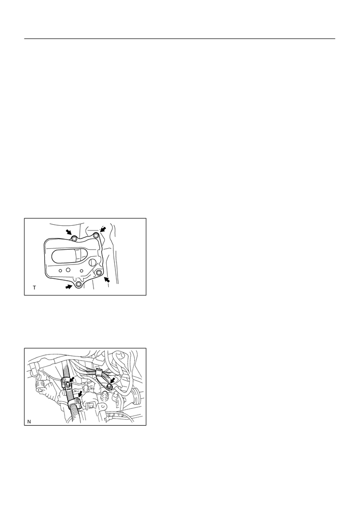
15. DISCONNECT WIRE HARNESS
(a) Disconnect the wire harness clamp.
(b) Remove the 2 bolts and disconnect the 2 wire harness
brackets.
C95746

41-18
MANUAL TRANSMISSION/TRANSAXLE
- MANUAL TRANSAXLE ASSY
(c)
Remove the 2 bolts and 2 ground cables.
C95747
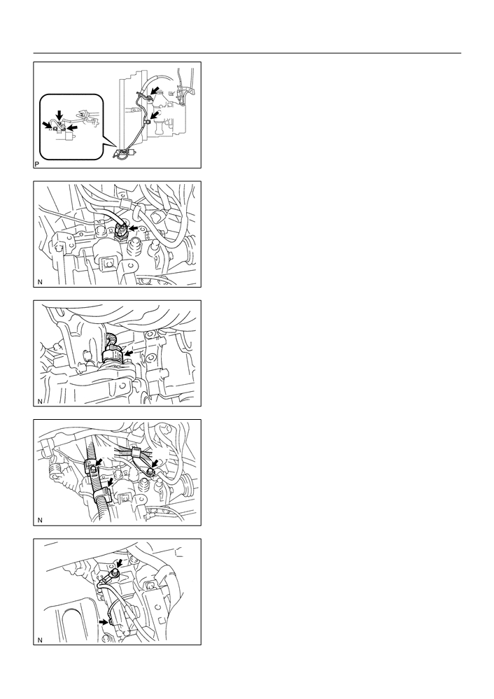
16. DISCONNECT CONNECTOR
(a) Disconnect the back-up lamp switch connector.
D11552
(b) w/o ABS:
Disconnect the speed sensor connector.
D11558
17. SEPARATE CLUTCH RELEASE CYLINDER ASSY
(a) Remove the 5 bolts, separate the release cylinder assy
with clutch piping from the transaxle.
D26730
18. SEPARATE FLOOR SHIFT CABLE TRANSMISSION
CONTROL SHIFT
(a) Remove the clip, washer and disconnect the shift cable
from the transaxle.
(b) Remove the clip and disconnect the shift cable from the
bracket.
D26696

41-19
MANUAL TRANSMISSION/TRANSAXLE
- MANUAL TRANSAXLE ASSY
19. SEPARATE FLOOR SHIFT CABLE TRANSMISSION
CONTROL SELECT
(a) Remove the clip, washer and disconnect the select cable
from the transaxle.
(b) Remove the clip and disconnect the select cable from the
bracket.
D26768
20. REMOVE STARTER ASSY
(a) Remove the nut and disconnect the starter wire.
(b) Disconnect the connector.
(c)
Remove the 2 bolts and starter assy.
D11561
21. SEPARATE STEERING INTERMEDIATE SHAFT (See page 51-18)
22. REMOVE FRONT DRIVE SHAFT ASSY LH (See page 30-6)
SST
09520-01010, 09520-24010 (09520-32040)
23. REMOVE FRONT DRIVE SHAFT ASSY RH
HINT:
Remove the RH side by the same procedures as LH side.
SST
09520-01010, 09520-24010 (09520-32040)
24. SEPARATE RETURN TUBE SUB-ASSY (See page 51-18)
SST
09023-12700
25. SEPARATE PRESSURE FEED TUBE ASSY (See page 51-18)
26. SUSPEND ENGINE ASSY
(a) Remove the 2 PCV hoses.
(b) Install the 2 hangers in the correct direction.
Parts No.:
Engine hanger: 12281-22021
No.1 engine hanger: 12281-15040
Bolt: 91512-B1016
Torque: 38 N m (387 kgf cm, 28 ft lbf)
F16861
(c)
Attach the engine chain hoist to the hangers.
CAUTION:
Do not attempt to hang the engine by hooking the chain to
any other part.
27. REMOVE FRONT SUSPENSION CROSSMEMBER SUB-ASSY (See page 26-13)
28. SUPPORT MANUAL TRANSAXLE ASSY
(a) Support the transaxle with a transmission jack.

41-20
MANUAL TRANSMISSION/TRANSAXLE
- MANUAL TRANSAXLE ASSY
29. REMOVE TRANSVERSE ENGINE ENGINE
MOUNTING INSULATOR
(a) Remove the 5 bolts, nut and engine mounting insulator
LH from the body.
D26699
30. REMOVE TRANSVERSE ENGINE ENGINE
MOUNTING BRACKET
(a) Remove the 3 bolts and engine mounting bracket LH from
the transaxle.
D26700
31. REMOVE MANUAL TRANSAXLE ASSY
(a) Remove the 6 bolts and transaxle from the engine.
C70065
32. REMOVE TRANSVERSE ENGINE ENGINE
MOUNTING BRACKET
(a) Remove the bolt, nut and engine mounting insulator FR
from the engine mounting bracket FR.
(b) Remove the 2 bolts and engine mounting bracket FR from
the transaxle.
C70063
33. REMOVE TRANSVERSE ENGINE ENGINE
MOUNTING BRACKET
(a) Remove the bolt and engine mounting insulator RR from
the engine mounting bracket RR.
(b) Remove the 3 bolts and engine mounting bracket RR
from the transaxle.
C70061

41-21
MANUAL TRANSMISSION/TRANSAXLE
- MANUAL TRANSAXLE ASSY
34.
INSTALL TRANSVERSE ENGINE ENGINE MOUNTING
(a)
(b)
BRACKET
(a)
Install the engine mounting bracket RR and 3 bolts to the
transaxle.
Torque: 64 N m (653 kgf cm, 47 ft lbf)
(b)
Install the engine mounting insulator RR and bolt to the
engine mounting bracket RR.
(a)
Torque: 87 N m (888 kgf cm, 64 ft lbf)
C70061
35.
INSTALL TRANSVERSE ENGINE ENGINE MOUNTING
BRACKET
(a)
(a)
Install the engine mounting bracket FR and 2 bolts to the
transaxle.
Torque: 64 N m (653 kgf cm, 47 ft lbf)
(b)
Install the engine mounting insulator FR, bolt and nut to
the engine mounting bracket FR.
(b)
Torque: 52 N m (530 kgf cm, 38 ft lbf)
C70063
36.
INSTALL MANUAL TRANSAXLE ASSY
A
A
(a)
Align the input shaft with the clutch disc and install the
B
transaxle to the engine.
B
(b)
Install the 6 bolts.
Torque:
Bolt A: 64 N m (650 kgf cm, 47 ft lbf)
Bolt B: 47 N m (480 kgf cm, 35 ft lbf)
C
Bolt C: 23 N m (230 kgf cm, 17 ft lbf)
C
C70065
37.
INSTALL TRANSVERSE ENGINE ENGINE MOUNTING
BRACKET
(a)
Install the engine mounting bracket LH to the transaxle
with the 3 bolts.
Torque: 52 N m (530 kgf cm, 38 ft lbf)
D26700
38. INSTALL TRANSVERSE ENGINE ENGINE MOUNTING
A
A
INSULATOR
(a) Install the engine mounting insulator LH with the 5 bolts
and nut.
Torque:
Bolt A: 52 N m (530 kgf cm, 38 ft lbf)
Bolt B: 80 N m (816 kgf cm, 59 ft lbf)
B
A
A
D26699

41-22
MANUAL TRANSMISSION/TRANSAXLE
- MANUAL TRANSAXLE ASSY
39. INSTALL FRONT SUSPENSION CROSSMEMBER SUB-ASSY (See page 26-13)
SST
09670-00010
40. CONNECT STEERING INTERMEDIATE SHAFT (See page 51-18)
41. INSTALL COLUMN HOLE COVER SILENCER SHEET (See page 51-18)
42. CONNECT RETURN TUBE SUB-ASSY (See page 51-18)
SST
09023-12700
43. CONNECT PRESSURE FEED TUBE ASSY (See page 51-18)
SST
09023-12700
44. INSTALL FRONT DRIVE SHAFT ASSY LH (See page 30-6)
45. INSTALL FRONT DRIVE SHAFT ASSY RH
HINT:
Install the RH side by the same procedures as LH side.
46. INSTALL STARTER ASSY
(a) Install the starter assy and 2 bolts to the transaxle.
(c)
Torque: 37 N m (378 kgf cm, 27 ft lbf)
(b) Connect the starter connector.
(a)
(c)
Install the wire and nut to starter assy.
(b)
Torque: 9.8 N m (100 kgf cm, 87 in. lbf)
(a)
D11561
47. CONNECT FLOOR SHIFT CABLE TRANSMISSION
CONTROL SHIFT
(a) Connect the shift cable end, and install the washer and
clip.
D26696
48. CONNECT FLOOR SHIFT CABLE TRANSMISSION
CONTROL SELECT
(a) Connect the select cable end, and install the washer and
clip.
D26768
41-23
MANUAL TRANSMISSION/TRANSAXLE
- MANUAL TRANSAXLE ASSY
49. CONNECT CLUTCH RELEASE CYLINDER ASSY
(a) Install the release cylinder with the 5 bolts.
A
Torque:
Bolt A: 25 N m (250 kgf cm, 19 ft lbf)
C
A
Bolt B: 12 N m (120 kgf cm, 9 ft lbf)
Bolt C: 5.0 N m (51 kgf cm, 44 in. lbf)
B
B
D26730
50. CONNECT CONNECTOR
(a) Connect the back-up lamp switch connector.
D11552
(b) w/o ABS:
Connect the speed sensor connector.
D11558
51. CONNECT WIRE HARNESS
(a) Install the 2 wire harness clamps to the transaxle with the
2 bolts.
A
B
Torque:
Bolt A: 25.5 N m (260 kgf cm, 19 ft lbf)
Bolt B: 12.8 N m (131 kgf cm, 9 ft lbf)
(1)
Connect the wire harness clamp.
F16859
(b) Install the 2 bolts and 2 ground cables.
Torque: 13 N m (133 kgf cm, 10 ft lbf)
F16860

41-24
MANUAL TRANSMISSION/TRANSAXLE
- MANUAL TRANSAXLE ASSY
52. INSTALL CRUISE CONTROL ACTUATOR ASSY (W/ CRUISE CONTROL) (See page
82-4)
53. INSTALL BATTERY CARRIER
(a) Install the battery carrier and 4 bolts.
Torque: 13 N m (133 kgf cm, 10 ft lbf)
C80159
54.
INSTALL BATTERY TRAY
55.
INSTALL BATTERY
56.
INSTALL BATTERY CLAMP SUB-ASSY
Torque:
Bolt: 5.0 N m (51 kgf cm, 44 in. lbf)
Nut: 3.5 N m (36 kgf cm, 31 in. lbf)
57.
INSTALL AIR CLEANER ASSY
Torque: 7.0 N m (71 kgf cm, 62 in. lbf)
58.
INSTALL CYLINDER HEAD COVER NO.2
Torque: 7.0 N m (71 kgf cm, 62 in. lbf)
59.
INSTALL HOOD SUB-ASSY
Torque: 13 N m (133 kgf cm, 10 ft lbf)
60.
INSPECT HOOD SUB-ASSY
61.
ADJUST HOOD SUB-ASSY (See page 75-1)
62.
ADD TRANSAXLE OIL (See page 41-2)
63.
INSPECT TRANSAXLE OIL (See page 41-2)
64.
BLEED POWER STEERING FLUID (See page 51-3)
65.
INSTALL FRONT WHEELS
Torque: 103 N m (1,050 kgf cm, 76 ft lbf)
66.
PLACE FRONT WHEELS FACING STRAIGHT AHEAD
67.
INSTALL EXHAUST PIPE (See page 15-2)
68.
INSTALL ENGINE UNDER COVER LH
69.
INSTALL ENGINE UNDER COVER RH
70.
INSPECT FRONT WHEEL ALIGNMENT (See page 26-5)
71.
CHECK ABS SPEED SENSOR SIGNAL (See page 05-297)
41-91
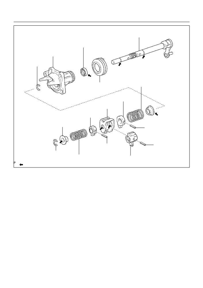
MANUAL TRANSMISSION/TRANSAXLE
- SHIFT & SELECT LEVER SHAFT ASSY (C59)
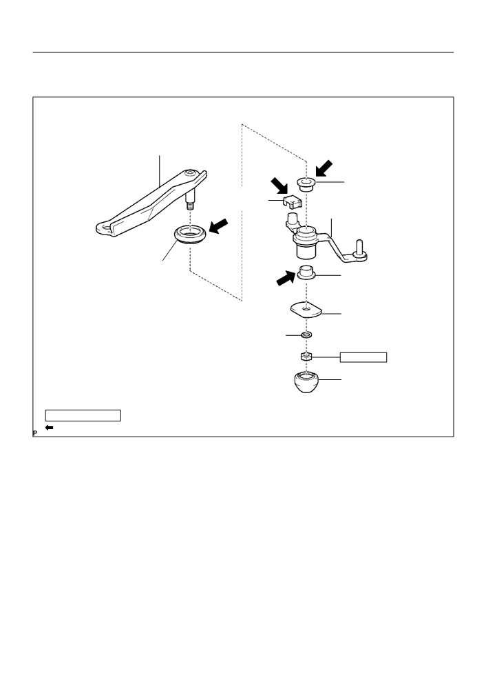
SHIFT & SELECT LEVER SHAFT ASSY (C59)
4107M-01
COMPONENTS
Selecting Bellcrank Support
Selecting Bellcrank
No.2 Bush
Control Shift
Lever Bush
Selecting Bellcrank No.2
Selecting Bellcrank
Selecting Bellcrank
Dust Cover No.2
No.2 Bush
Selecting Bellcrank
No.2 Plate Washer
Washer
11.8 (120, 9)
Selecting Bellcrank
Dust Cover No.1
Nm (kgfcm, ftlbf)
: Specified torque
Apply MP grease
C94578
41-92
MANUAL TRANSMISSION/TRANSAXLE
- SHIFT & SELECT LEVER SHAFT ASSY (C59)
Shift & Select Lever Shaft
_ Control Shaft Cover Oil Seal
Control Shaft Cover
Snap Ring
Shift & Select Lever Shaft Boot
Compression Spring
Select Inner Lever
Shift Inter Lock Plate
Shift Lever Inner No.2
Select Spring Seat No.2
Slotted Spring Pin
Slotted Spring Pin
Slotted Spring Pin
E-ring
Compression Spring
Shift Inner Lever No.2
_ Non-reusable part
Apply MP grease
D12109

41-93
MANUAL TRANSMISSION/TRANSAXLE
- SHIFT & SELECT LEVER SHAFT ASSY (C59)
4107N-01
OVERHAUL
1.
REMOVE CONTROL SHIFT LEVER BUSH
(a) Remove the control shift lever bush from the selecting
bellcrank assy.
C80760
2.
REMOVE SELECTING BELLCRANK DUST COVER
NO.1
(a) Remove the selecting bellcrank dust cover No.1 from the
selecting bellcrank assy.
C80761
3.
REMOVE SELECTING BELL CRANK NO.2
(a) Remove the nut, spring washer and selecting bellcrank
No.2 plate washer.
(b) Remove the selecting bellcrank No.2 from the selecting
bellcrank support.
C80762
4.
REMOVE SELECTING BELLCRANK DUST COVER
NO.2
(a) Remove the selecting bellcrank dust cover No.2 from the
selecting bellcrank No.2.
C80763

41-94
MANUAL TRANSMISSION/TRANSAXLE
- SHIFT & SELECT LEVER SHAFT ASSY (C59)
5.
REMOVE SELECTING BELLCRANK NO.2 BUSH
(a) Remove the 2 selecting bellcrank No.2 bushes from the
selecting bellcrank No.2.
C80571
6.
REMOVE SELECT SPRING SEAT NO.2
(a) Using a screwdriver, remove the E-ring, select spring
seat No.2 and select return spring No.2 from the shift &
select lever shaft.
C80572
7.
REMOVE SHIFT LEVER INNER NO.2
(a) Using a pin punch (f 5 mm) and a hammer, remove the
slotted pin and shift lever inner No.2 from the shift & select
lever shaft.
HINT:
Make sure the orientation of the shift lever inner No.2.
C80573
8.
REMOVE SHIFT LEVER INNER NO.1
(a) Using a pin punch (f 5 mm) and a hammer, remove the
slotted pin, shift lever inner No.1 and shift inter lock plate
from the shift & select lever shaft.
HINT:
Make sure the orientation of the shift lever inner No.1.
C80574
9.
REMOVE SELECT INNER LEVER
(a) Using a pin punch (f 5 mm) and a hammer, remove the
slotted pin, select inner lever, select return spring No.1
and select return spring seat No.1.
HINT:
Make sure the orientation of the select inner lever.
C80575

41-95
MANUAL TRANSMISSION/TRANSAXLE
- SHIFT & SELECT LEVER SHAFT ASSY (C59)
10. REMOVE CONTROL SHAFT COVER
(a) Using 2 screwdrivers and a hammer, tap out the snap
ring.
(b) Remove the control shaft cover and shift & select lever
shaft dust boot.
C95740
11. REMOVE CONTROL SHAFT COVER OIL SEAL
(a) Using a screwdriver, remove the control shaft cover oil
seal from the control shaft cover.
C95742
12. INSTALL CONTROL SHAFT COVER OIL SEAL
SST
(a) Using SST and a hammer, install a new control shaft cov-
er oil seal to the control shaft cover.
SST
09950-60010 (09951-00220), 09950-70010
(09951-07100)
Drive in depth: 0.7
0.5 mm (0.0276
0.0197 in.)
(b) Coat the lip of control shaft cover oil seal with MP grease.
C94255
13. INSTALL CONTROL SHAFT COVER
(a) Coat the shift & select lever shaft boot with MP grease,
install it to the control shaft cover.
(b) Install the control shaft cover to the shift & select lever.
HINT:
Install the dust boot with the projection up and the hole side
down.
(c)
Coat the shift & select lever shaft with MP grease.
C94256
(d) Using a brass bar and a hammer, tap in the snap ring to
the shift & select lever shaft.
C95742