Subaru XV Crosstrek (2016 year). Instruction - part 17
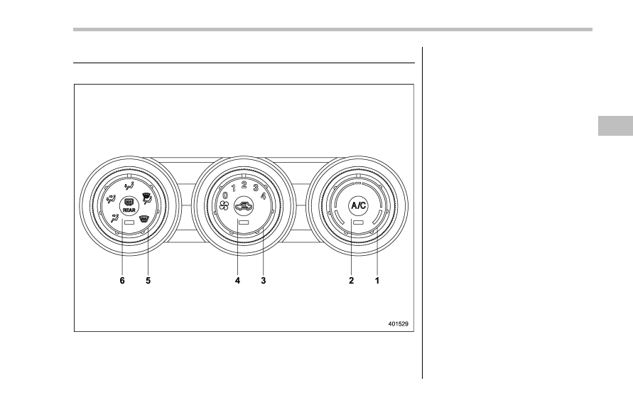
Climate control panel
& Type A
1)
Temperature control dial (Refer to
“Tem-
perature control
” F4-9.)
2)
Air conditioner button (Refer to
“Air
conditioner control
” F4-10.)
3)
Fan speed control dial (Refer to
“Fan
speed control
” F4-10.)
4)
Air inlet selection button (Refer to
“Air
inlet selection
” F4-10.)
5)
Airflow mode selection dial (Refer to
“Airflow mode selection” F4-8.)
6)
Rear window defogger button (Refer to
“Defogger and deicer” F3-108.)
Climate control/Climate control panel
– CONTINUED –
4-3