SsangYong Rexton. Service manual - part 636
SSANGYONG Y200
7D-10 AUTOMATIC CONTROL HVAC SYSTEM
Intake Control Door Motor
The mode motor set the I/A mode by the control signal
of the AUTO temperature control.
When the mode displayed in the AUTO temperature
control is different from the actual mode, check the
followings;
•
Turn the ignition ON.
•
Measure the voltage between the (+) terminals at
each mode and verify that changes from 0V before
the mode selection to 12V after the mode selection.
•
If the value is the specified value, check the open
or short circuit.
•
I f t h e w i r i n g i s n o r m a l , r e p l a c e t h e A U T O
temperature control.
•
If the voltage value is outside the specified value,
replace the I/A mode motor.
•
Check the motor operation connecting the (+)
terminal to No.4 of the motor connector and
connecting No.5 and No.7 to (-) terminal sequentially
using 12 V power.
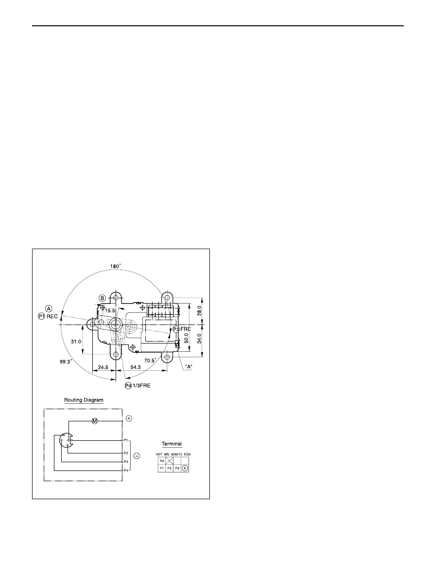
Inspection
When the vent inlet mode displayed in the AUTO
temperature control is different from the actual mode,
check the followings;
1. Turn the ignition ON.
2. Measure the voltage between positive terminal and
negative terminal of the Mtr-Act, AI connector.
(Specified value; 12 V)
3. Measure the voltage between P1, P2, P3 and (+)
terminal. (If it changes from 0V before the mode
selection to 12 V after the mode selection, it’s
normal)
4. If the value is outside the specified value, check
the open or short circuit.
5. I f t h e w i r i n g i s n o r m a l , r e p l a c e t h e A U T O
temperature control.
6. If the value is the specified value, replace the Mtr-
Act, AI.
7. Check the motor operation connecting the (+)
terminal to No.4 of the motor connector and
connecting No.5 and No.7 to (-) terminal sequentially
using 12 V power.
Mode Control Motor
The control motor sets the mode of Vent, Bi-level, Foot,
Foot/Def or Def by opening/closing the outlet damper
at the outlet of Vent, Foot or Def according to control
signal of the AUTO temperature control.
YAD7D120