SsangYong Rexton. Service manual - part 635


  Index      SsangYong     SsangYong Rexton - service and repair manual


Search            


Content   ..  633  634  635  636   ..


SsangYong Rexton. Service manual - part 635


SSANGYONG  Y200

7D-6  AUTOMATIC CONTROL HVAC SYSTEM

Step

1

2

3

4

5

6

Blower Voltage

4.5 V

6.0 V

7.5 V

9.0 V

11.0 V

Max Hi

*

The voltage of the blower motor may increase or
decrease (0.5 V) according to power voltage.
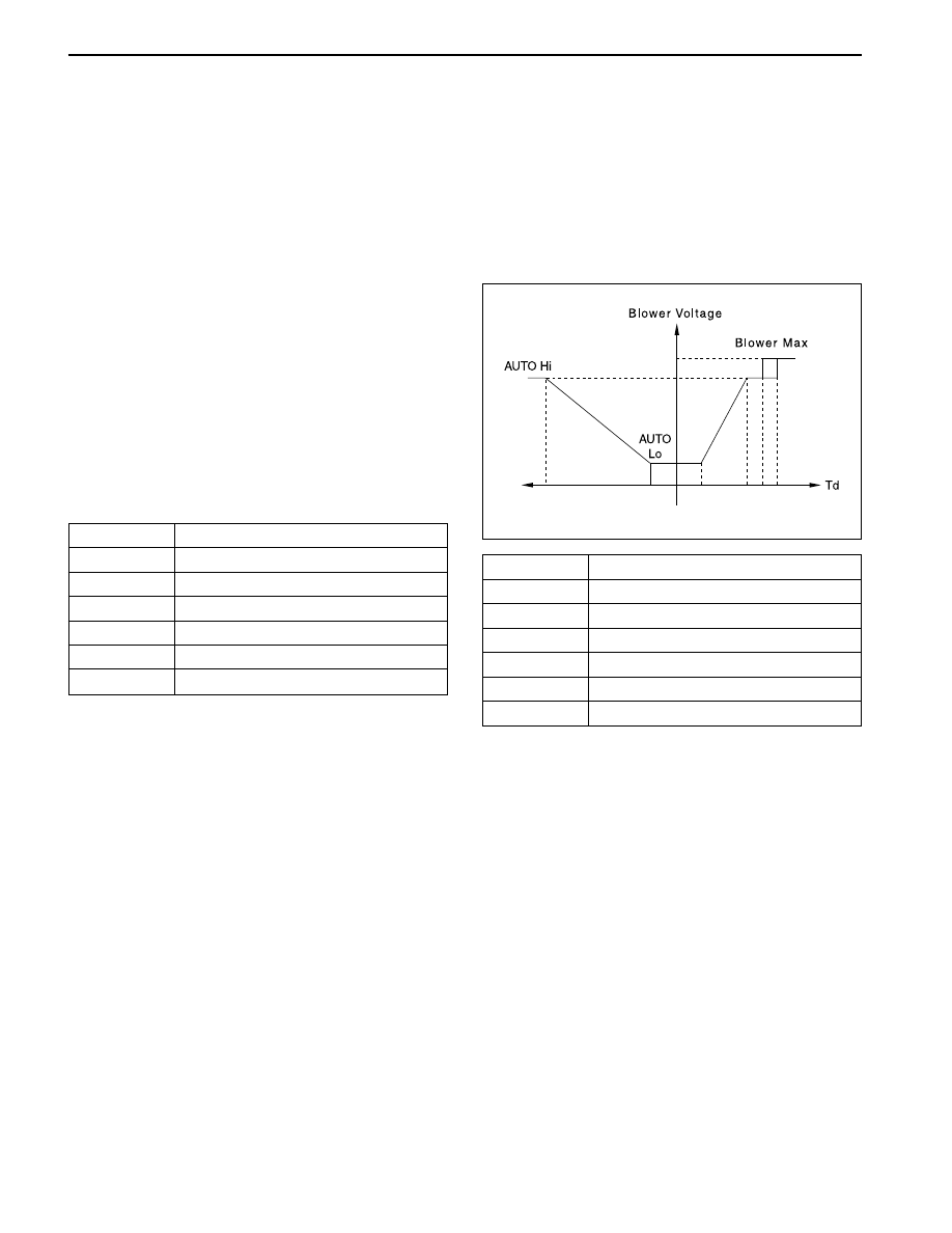
Automatic Control

Td value can be determined by the set temperature
value and Td value is set to the target voltage of the
blower motor simultaneously. The blower motor can
shift without step.

Abbreviation: Td (Thermal Demand) : Td value is
the default for automatic control of the automatic
temperature control and allows it to control the set
temperature calculating the differences between
inside air temperature and ambient temperature.

Blower Step

1

2

3

4

5

6

Blower Motor Voltage

4.0 - 5.5 V

5.5 - 7.5 V

7.5 - 8.5 V

8.5 - 9.5 V

9.5 - 10.5 V

10.5 - 13.5 V

Vent Rate Control By Heating Operation

When the temperature of the engine coolant is low or
it’s difficult to obtain the desired hot air in winter, the
system controls to prevent the cold airflow from the
outlet due to the cold air give a negative effect to the
heating performance.

Therefore vent step is fixed 1st on blower AUTO step
until the coolant sensor detects above 20 ° C and also
the blower step increases gradually according to going
up the coolant temperature. When the coolant
temperature goes up above 40  ° C, the heating
operation stops.

Vent Rate Control By Cooling Operation

When the air inside the resonance duct is hot in summer,
after the system keeps the low vent rate (1st) operating
for 5 seconds and discharges the hot air to the
windshield side (Def Mode), the system starts to control
normally in order to avoid for the passengers contacting
the hot air.

SYSTEM BASIC FUNCTION

Set Temperature Control

When you set the setting temperature using the
temperature control switch, the FATC receives the
various input signals from sensors including the
information of inside air temperature, ambient
temperature, coolant temperature and sun loads etc..
The FATC uses this signals to control automatically
the A/C compressor, the mode door, the I/A door, air
mix door and blower motor etc.

Airflow Control

For setting at Full AUTO, it is possible to control the
b l o w e r   m o t o r   o p e r a t i o n   b o t h   m a n u a l l y   a n d
automatically in order to adjust the airflow according
to the set temperature.

Manual Control

When you push the blower switch, you can control the
blower motor manually and it increases or decreases
each step by moving the switch to HI/LO. (with the
ignition ON)

YAD7D040

AUTOMATIC CONTROL HVAC SYSTEM  7D-7

SSANGYONG  Y200

Defroster Calibration

On the blower AUTO step, when the passenger sets
to Defroster (Def), the system increases the blower
voltage by 2 V for some intervals comparing AUTO
voltage. But it is excluded the condition when the
blower voltage is above 11.0 V. Also, the voltage
increasing by defroster calibration is limited up to 10.5 V.

Vehicle Speed Calibration

On the Ambient or the 1/3 Ambient and the blower
AUTO, the blower decreases the voltage with the
vehicle speed 100 Km/h such as 1.5 V for the Ambient,
1.0 V for the 1/3 Ambient.

But it is the exception for the blower max.

Ambient Temperature Display

It indicates the ambient temperature as 0.5  ° C
increment in the set temperature digit by ambient
temperature sensor.

When you push the AMB key it indicates the ambient
temperature for 5 seconds and return back the set
temperature.

If you push the AMB key again during indicating in
5 seconds, it returns back.

The ambient temperature sensor is securing in the
front of radiator and may be influenced easily to
the heat of the engine compartment in parking.
Therefore the ambient temperature sensor indicates
the ambient temperature accurately on the condition
of above 40 km/h running.

Delivery Condition

For the initial installation (the initial current draw), the
initial mode follows;

Vent inlet Control

Manual Control

When you push the I/A control switch, you can control
the I/A door manually and the I/A door changes
between the recirculation air and the fresh air flow
alternately by the control switch. For changing the fresh
air step (FRE) to the recirculation air step (REC), the
blower voltage decrease 15% and for changing the
recirculation air step (REC) to the fresh air step (FRE),
the blower voltage return back.

AUTO Control

Control by the Vehicle Speed

The system controls the vent inlet according to the
vehicle speed in order to prevent the exhaust gas of
the preceding vehicle from flowing inside with the
vehicle stopping or driving at low speed. The operation
and control condition is following as;

1. When the vent inlet mode is AUTO and the A/C

“ON”.

2. When the vehicle keeps to drive at below 10 km/h

for 10 seconds and changes the REC mode at stop.

3. If 10 minutes passes after changing the REC mode,

it returns back to the AUTO mode.

Actuator

Mode

Suction

Air

A/C

Blower

Mix

Condi-

tion

FOOT/

DEF

FRESH

OFF

OFF

Td Basic

Control

YAD7D050

YAD7D060

YAD7D070

SSANGYONG  Y200

7D-8  AUTOMATIC CONTROL HVAC SYSTEM

Vent outlet Control

Manual Control

For pushing the mode switch of AUTO temperature
control, you can select four type of the vent outlets.

When you push the Def switch, it keeps to change to
the defroster mode regardless of the sequence.

AUTO Control

A/C Control

Manual Control

When you pushed the A/C switch “ON” or the Def
switch “ON”, A/C starts to operate.

AUTO Control

Basic Control: A/C “ON” has the priority for the initial
operation.

Full Cold/Hot Control

When you sets the set temperature to full cold (LO) or
full hot (HI), the system controls the temperature to
full cold or full hot regardless of sensor’s detection.
For LO, it becomes A/C “ON”, front vent mode,
recirculation air, max blower speed, air mix door close
and for HI, A/C “OFF”, floor vent mode, ambient mode,
air mix door open.

Wiper Calibration Control

It is possible to generate the frost on the windshield in
the rainy days. At this time, FATC controller allows the
mode to change the AUTO defroster mode.

Operation Condition: When the passenger operates
the wiper on AUTO mode, the system controls the
wiper on the A/C AUTO mode after sending the
wiper signal and controlling the delay for 1 minutes.

FATC Controller Illumination Control

When the tail lamp is ON, ATC Controller illumination
lamp turns on.

SYSTEM COMPONENTS -
CONTROL

Controller Assembly

The operation of the A/C system is controlled by the
switched on the control head. This console-mounted
controller consist of control knobs and a vacuum
fluorescent display (VFD) indicating the status of the
control settings selected.

Sensors and Motors

Inside air sensor, ambient sensor, coolant
temperature and sun sensor

Door mode motor, intake air control door motor, air
mix door motor

Inside Air Sensor

Inside air sensor located in left side of full automatic
temperature control (FATC) controller, is a sensor that
detects the interior air temperature and a thermistor
that decreases its resistance when temperature up and
increases when temperature down. If there is open or
short in the sensors, 25 ° C (77 ° F) will be substitute.

Inspection

When the inside air temperature sensor error displays,
check the followings;

YAD7D080

YAD7D090

YAD7D100

AUTOMATIC CONTROL HVAC SYSTEM  7D-9

SSANGYONG  Y200

1. Remove the inside air temperature sensor and

measure the resistance between the sensor
connectors.

(approximately 2.2 K

 at 25 

°

C) Replace the inside

air temperature sensor when the resistance value
is excessive low or high.

2. Replace the inside air temperature sensor for

outside the specified value and check the
followings for within the specified value;

3. Turn the ignition ON.

4. Measure the voltage between A13 and A16 terminal

of the AUTO temperature control connector.
(approximately 2.2 V at 25 

°

C)

5. Verify the open circuit of the wiring harness when

you can not measure the voltage value and replace
the AUTO temperature control when it’s normal.

Ambient Sensor

Ambient sensor is a thermistor (NTC resistance) that
decreases its resistance when temperature up and
increases when temperature down and it detects
ambient air temperature. If there is open or short in
the sensors, 25  ° C (77  ° F) will be substitute. The
sensor is located in the left back side of front bumper.

Inspection

When the ambient temperature sensor error displays,
check the followings;

1. Remove the ambient temperature sensor and then

measure the resistance between the sensor
connectors.

(approximately 2.2 K

 at 25 

°

C) Replace the

ambient temperature sensor when the resistance
value is excessive low or high.

2. Replace the ambient temperature sensor for outside

the specified value and check the followings for
within the specified value;

3. Turn the ignition ON.

4. Measure the voltage between A13 and B8 terminal

of the AUTO temperature control connector.
(approximately 2.2 V at 25 

°

C)

5. Verify the open circuit of the wiring harness when

you can not measure the voltage value and replace
the AUTO temperature control when it’s normal.

Coolant Temperature Sensor

Coolant temperature sensor is a thermistor that
decreases its resistance when temperature up and
increases when temperature down. It detects coolant
temperature to operate the blower speed at low when
the coolant temperature is less than 50 ° C (122 ° F). If
the coolant temperature sensor is open or short, 100
° C (212 ° F) will be substitute.

Inspection

When the coolant temperature sensor error displays,
check the followings;

1. Measure the resistance between the sensor

connectors. (approximately 2.2 K

 at 25 

°

C)

2. Replace the coolant temperature sensor for outside

the specified value and check the followings for
within the specified value;

3. Turn the ignition ON.

4. Measure the voltage between A13 and B9 terminal

of the AUTO temperature control connector.
(approximately 2.2 V at 25 

°

C)

5. Verify the open circuit of the wiring harness when

you can not measure the voltage value and replace
the AUTO temperature control when it’s normal.

Sun Sensor

Sun sensor is a photo diode that detects lights.
Resistance of the diode can be measured as current
by using voltmeter according to increasing sun loads.
If the sun sensor is error, no sun load will be substitute.

Photo Diode

It is used to the circuit converting the sun light loads
to the electric signals.

Inspection

When the sun sensor error displays, check the
followings;

1. Remove the sensor to place it under the sun light

and measure the current between the connector
terminals.

2. Place the sun sensor under the shadow place and

measure the current between the connector
terminals. If the value is lower than the value under
the sun light, it’s normal.

3. Turn the ignition ON.

4. Measure the voltage between A13 and B10 terminal

of the AUTO temperature control connector. (Sun
light; 2.5 V, Shadow; 4.8 V)

5. Verify the open circuit of the wiring harness when

you can not measure the voltage value and replace
the AUTO temperature control when it’s normal.

YAD7D110


Content   ..  633  634  635  636   ..