SsangYong Rexton. Service manual - part 606


  Index      SsangYong     SsangYong Rexton - service and repair manual


Search            


Content   ..  604  605  606  607   ..


SsangYong Rexton. Service manual - part 606


SSANGYONG  Y200

5D2-72  TRANSFER CASE - TOD

03E-019

03E-019

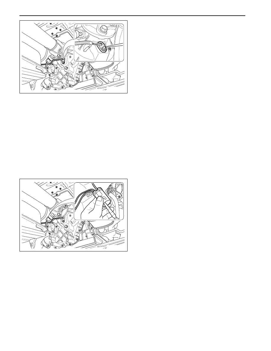
7. Detach sensor from transfer case by lifting up

using tool.

Notice: When disconnect sensor, make sure on
adequate pressure due to sensitiveness with
shock.

8. Disconnect taping from both protection tube ends

that wrap 3 wires of speed sensor and 1 wire of
clutch coil.

9. Disconnect tube.

10. Disconnect pin and wire from speed sensor

connector by pulling sticking long-nose plier into
“L” pin in connector.

11. On the same way, disconnect pin and wire “M”

and “N” from connector.

Notice: Do not touch the wires related with EMC.

12. Prepare new speed sensor.

13. Connect 3 pins with wires of speed sensor to

coincide with each connection position.

14. Using long-nose plier, connect tightly by pulling

pins.

15. Apply rubber cap into connector using long-nose

plier not to detach.

16. Connect protection tube with wire.

17. Tape both ends of tube.

18. Putting rear speed sensor into hole, connect

exactly pushing both ends.

19. Screw 1 unit of bolt (M10).

YAD5D340

YAD5D350

TRANSFER CASE - TOD  5D2-73

SSANGYONG  Y200

Installation Notice

20. Connect speed sensor connector, then locking

sleeve.

Notice: Front propeller shaft should be premised
by removal of shift motor.
After disconnecting shift motor, procedure of
replacement on sensor assembly of accords with
one of rear speed sensor.

Tightening Torque

3 - 6 N•m

 (27 - 53 lb-in)

SSANGYONG  Y200

5D2-74  TRANSFER CASE - TOD

UNIT REPAIR

TRANSFER CASE, DISASSEMBLED VIEW

YAD5D360

TRANSFER CASE - TOD  5D2-75

SSANGYONG  Y200

1 Bearing
2 Bushing
3 Carrier Assembly
4 Sun Gear
5 Thrust Plate
6 Input Shaft
7 Output Shaft Thrust Washer
8 Bearing
9 Snap Ring

10 High-low Collar
11 Rear Output Shaft
12 Oil Strainer
13 Coupling Hose
14 Hose Clamp
15 Pump Assembly
16 Thrust Washer
17 Sprocket, Drive (24T)
18 Clutch Pack Assembly
19 Insulator Washer
20 Armature
21 Snap Ring
22 Wave Washer
23 Apply Cam
24 Ball
25 Cam and Coil Assembly
26 Nut (2)
27 Output Shaft Yoke Washer
28 Oil Seal
29 Case Flange
30 Bolt
31 Upper Speed Sensor (Rear)
32 Nut
33 Washer
34 Bolt (M10 X 105 X 30)
35 Tag, Identification
36 Thrust Bearing
37 Clutch Coil Assembly
38 Fork, Reduction Shift

39 Shift Rail
40 Shaft, Shift
41 Spacer
42 Torsion Spring
43 Electric Shift Cam
44 Transfer Case Shift Motor
45 Bolt
46 J-clip
47 Connector Retainer
48 Bolt
49 Support Stud
50 Lower Speed Sensor (Front)
51 Plug
52 Identification Decal
53 Cover
54 Tone Wheel, Lower
55 Chain, Drive
56 Sprocket, Driven (24T)
57 Magnet, Oil Pan
58 Case
59 Case Flange and Output Shaft
59 Case Assembly
60 Breather Bar
61 Spiral Pin
62 Oil Seal
63 Pin, Dowel
64 Ring Gear
65 Retaining Ring
66 Snap Ring
67 Bearing
68 Snap Ring
69 Bearing
70 Speedometer Drive Gear
71 Facing, Shift Fork
72 Upper Tone Wheel
73 Oil Seal
74 Bearing Sleeve
75 Bearing


Content   ..  604  605  606  607   ..