SsangYong Rexton. Service manual - part 502
FRONT BRAKE 4B-13
SSANGYONG Y200
YAD4B240
YAD4B250
YAD4B260
UNIT REPAIR
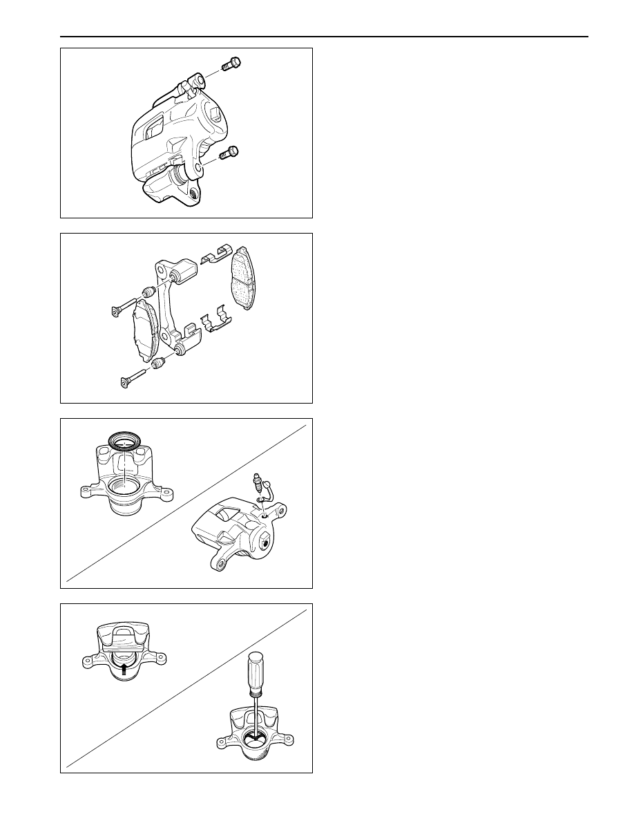
BRAKE CALIPER
Disassembly Procedure
1. Remove the caliper assembly.
2. Separate the cylinder assembly and carrier.
•
Remove the guide rod bolt.
•
Separate the cylinder assembly and carrier.
3. Disassemble the carrier.
•
Remove the pad.
•
Remove the spring.
•
Remove the guide rod and the boot.
4. Remove the cylinder assembly.
•
Remove the bleeder plug.
•
Remove the bleeder plug cap.
•
Remove the piston boot.
YAD4B270
•
Using the compressed air, blow out the piston
from housing.
Notice: Do not face in the direction of removing.
•
Remove the piston.
•
Remove the piston seal.