SsangYong Rexton. Service manual - part 493


  Index      SsangYong     SsangYong Rexton - service and repair manual


Search            


Content   ..  491  492  493  494   ..


SsangYong Rexton. Service manual - part 493


SSANGYONG  Y200

4A-2  BRAKE SYSTEM

DESCRIPTION AND OPERATION

BRAKING SYSTEM TESTING

Brakes should be tested on a dry, clean, reasonably
smooth and level roadway. A true test of brake
performance cannot be made if the roadway is wet,
greasy or covered with loose dirt which can cause tires
not to grip the road unequally. Testing also will be
inaccurate on a crowned roadway because the wheels
tend to bounce.

Test the brakes at different vehicle speeds with both
light-and heavy-pedal pressure; however, avoid locking
the brakes and sliding the tires. Locked brakes and
sliding tires do not indicate brake efficiency since
heavily braked but turning wheels will stop the vehicle
in less distance than locked brakes. More tire-to-road
friction is present with a heavily braked, turning tire
than with a sliding tire.

There are three major external conditions that affect
brake performance:

Tires having unequal contact and grip of the road
will cause unequal braking. Tires must be equally
inflated and the tread pattern of the right and the
left tires must be approximately equal.

Unequal loading of the vehicle can affect the brake
performance since the most heavily loaded wheels
require more braking power and thus more braking
effort than the others.

Misalignment of the wheels, particularly conditions
of excessive camber and caster, will cause the
brakes to pull to one side.

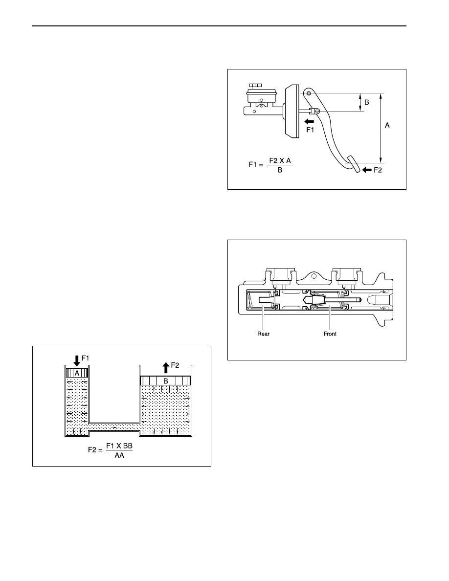
HYDRAULIC BRAKE SYSTEM

BRAKE PEDAL

YAD4A010

This system uses the principle of the leverage and
PASCAL’s. When you pushes the brake pedal, the
pressure by adapting the pedal increases through the
power booster and delivers it into the master cylinder
to generate hydraulic pressure.

Hydraulic pressure generated by the master cylinder
delivers to the caliper through the brake pipe or hose.
This hydraulic pressure allows the caliper pad to push
the disc plate. Thus it generates the braking forces.

YAD4A020

Brake pedal uses the principle of the leverage and
increases the pressure into the master cylinder in order
to generate the braking forces.

MASTER CYLINDER

The master cylinder is designed for use in a diagonally
split system. One front and one diagonally opposite
rear brakes are served by the primary piston. The
opposite front and rear brakes are served by the
secondary piston.

The master cylinder incorporates the functions of the
standard dual master cylinder, plus a low fluid level
indicator and the proportioning valves in the non-
antilock braking system. The proportioning valves limit
the outlet pressures to the rear brakes after a
predetermined master cylinder pressure has been
reached. The brake master cylinder sensor is attached
under the body of the plastic brake master cylinder
reservoir.

YAD4A030

BRAKE SYSTEM  4A-3

SSANGYONG  Y200

YAD4A040

BRAKE BOOSTER

The brake booster is a double-diaphragm, vacuum-
suspended unit. In normal operating mode, with the
service brakes in the release position, a vacuum-
suspended booster operates with a vacuum on both
sides of its diaphragm. When the brakes are applied,
air at atmospheric pressure is admitted to one side of
the diaphragm to provide the power assist. When the
brakes are released, atmospheric air is shut off from
that side of the diaphragm. The air is then drawn from
the booster through the vacuum check valve by the
vacuum source.

1. Pressure Distribution At working

When it pushes the brake pedal, the booster pushrod
(1) pushes the poppet (2) and valve plunger (3) and
the poppet (2) goes closely to the power piston (5)
resulting in closing the vacuum valve (9). The power
cylinder (A) and (B) is isolated and the valve plunger
(3) is separated from the poppet (2). And then the air
valve (6) opens in order to flow air into (B) through the
filter and thus, the power piston (5) enables to push
t h e   m a s t e r   c y l i n d e r   p u s h r o d   ( 7 )   f o r   p r e s s u r e
distribution.

2. Pressure Distribution After working

When it pushes off the brake pedal, the valve plunger
(3) returns back to the original position by return spring
(4) resulted in closing the air valve (6) and open the
vacuum valve (9) in order to balance the pressures
between (A) and (B) of the power cylinder. And then
the power piston (5) returns back to the original position
by the master cylinder reaction and the diaphragm
return spring (8) pressure.

YAD4A050

SSANGYONG  Y200

4A-4  BRAKE SYSTEM

SPECIFICATIONS

Drum Type


Drum Type

Ø 254

55 x 243

Drum Type

4.3 : 1

138 mm

1 ~ 4 mm

Ø 25.4 mm

7 : 1

Drum Type

Ø 254 mm

55 x 243 x 5 mm

Pedal Ratio

Pedal Stroke

Pedal Freeplay

Inner Diameter

Ratio

Type

I.D of Drum

Lining

Type

Type

Spec.

Application

Brake Pedal

Master Cylinder

Brake Booster

Front Brake

Rear Brake

Parking Brake

Brake Fluid

MANDO Brake

KDAC Brake

Disc Type


Solid Disc

-

-

Disc Type

-

-

-

-

-

Rear Wheel Internal Expansion

Mechanical

DOT4 or DOT3

Type

Tandem Type

(/W Lever Sensor)

-

Type

Vacuum Booster

Type

I.D. of Caliper

Cylinder

-

Ø 60 mm

-

Ø 60 mm

Thickness of

Brake Pad

-

10 mm

-

Thickness of

Disc Plate

-

24 mm

-

Shoe Type

Leading End

Trailing Type

-

Leading End

Trailing Type

-

I.D. of Wheel

Cylinder

Ø 23.87 mm

-

Ø 23.81 mm

-

I.D. of Caliper

Cylinder

-

Ø 42.9 mm

-

Ø 42 mm

Thickness of

Brake Pad

-

10 mm

-

10 mm

Thickness of

Disc Plate

-

10.4 mm

-

10.4 mm

Type

-

Ventilated

Disc Type

-

BRAKE SYSTEM  4A-5

SSANGYONG  Y200

Repair

Retighten

Replace

Clean

Replace

Repair

Repair

Lubrication

Retighten

Adjust

Repair

Replace

Replace

Repair

Repair

Replenish or Replace

Bleeding

Repair

Repair

Replace

Repair

Repair

Repair

Repair

Bleeding

Repair

Adjust

Repair

Adjust

Replace

Repair

Replace

Lubrication

Replace

Adjust

Replace

Replace

Replace

Repair

Adjust Lever Travel or

Check the Cable

Incorrectly Mounted Back Plate or Caliper

Loosened Bolt of Back Plate or Caliper

Crack or Uneven Wear of Brake Drum or Disc

Foreign Material Inside the Brake Drum

Pad or Lining Sticking to Contact Surface

Excessive Clearance Between Caliper and Pad

Uneven Contact of Pad

Lack of Lubrication

Loosened Suspension

Incorrect Tire Pressure Between Left and Right

Poor Contact of Pad or Lining

Oil or Grease is Applied to Pad or Lining

Bent or Uneven Wear of Drum

Incorrectly Mounted Wheel Cylinder

Faulty Auto Adjuster

Dirty or Lack of Fluid

Air in Brake System

Faulty Brake Booster

Poor Contact of Pad or Lining

Oil or Grease on Pad

Faulty Auto Adjuster

Over Heated Rotor Due to Dragging Pad or Lining

Clogging Brake Line

Faulty Proportioning Valve

Air in Brake System

Fluid Leaking

Excessive Clearance Between Push Rod and M/Cylinder

Parking Brake is not Fully Released

Incorrect Adjustment of Parking Brake

Weak Return Spring of Brake Pedal

Incorrect Pedal Free-play

Broken Rear Drum Brake Shoe Return Spring

Lack of Lubrication

Damaged Master Cylinder Check Valve or Piston
Return Spring

Insufficient Clearance Between Push Rod and Master
Cylinder

Worn Brake Lining

Dirty Brake Lining Surface by Grease or Oil

Binding Parking Brake Cable

Faulty Auto Adjuster

Excessive Lever Stroke

Noise Or Vehicle Vibration
When Applied Brake

DIAGNOSTIC INFORMATION AND PROCEDURES

Symptom

Check

Action

Pulls To One Side When
Braking

Poor Braking

Increasing Pedal Stroke
 (Pedal Goes To Floor)

Brake Dragging

Poor Parking Brake


Content   ..  491  492  493  494   ..