SsangYong Rexton. Service manual - part 441


  Index      SsangYong     SsangYong Rexton - service and repair manual


Search            


Content   ..  439  440  441  442   ..


SsangYong Rexton. Service manual - part 441


SSANGYONG  Y200

1F2-90  M161 ENGINE CONTROLS

Notice: Before removal, the fuel rail assembly may
be  cleaned with a spray-type cleaner, following
package instructions. Do not immerse the fuel rails
in liquid cleaning  solvent. Use care in removing
the fuel rail assembly to prevent damage to the
electrical connectors and injector  spray tips.
Prevent dirt and other contaminants from entering
open lines and passages. Fittings should  be
capped and holes plugged during service.

Important: If an injector becomes separated from
the rail and remains in the cylinder head, replace
the injector O-ring seals and the retaining clip.

12. Remove the injectors and the fuel rail carefully.

13. Remove the fuel injector retainer clips.

14. Remove the fuel injectors by pulling them down

and out.

15. Discard the fuel injector O-rings.

16. Lubricate the new fuel injector O-rings with engine

oil. Install the new O-rings on the fuel injectors.

17. Perform a leak check of the fuel rail and fuel

injectors.

18. Installation should follow the removal procedure

in the reverse order.

YAA1F770

YAA1F780

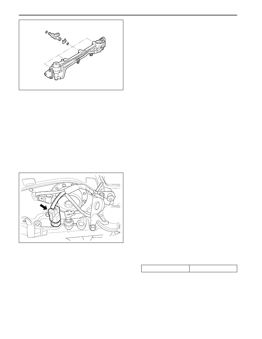
ENGINE COOLANT  TEMPERATURE
SENSOR

Removal and Installation Procedure

1. Relieve the coolant system pressure.

2. Disconnect the negative battery cable.

3. Disconnect the engine coolant temperature sensor

connector.

Notice:  Take care when handling the engine
coolant temperature sensor. Damage to the sensor
will affect the proper operation of the fuel injection
system.

4. Remove the engine coolant temperature sensor

from the pump hosing.

Installation Notice

Tightening Torque

30 N•m (22 lb-ft)

5. Installation should follow the removal procedure

in the reverse order.

M161 ENGINE CONTROLS  1F2-91

SSANGYONG  Y200

THROTTLE BODY (INTEGRATED
WITH  THE ACTUATOR)

Removal and Installation Procedure

1. Disconnect the negative battery cable.

2. Disconnect the intake air temperature (IAT) sensor

connector.

3. Remove the intake air duct clamps.

KAC1F250

KAA1D240

6. Disconnect the throttle body electrical connector.

7. Remove the throttle body bolts.

Installation Notice

9. Remove the throttle body and discard the gasket.

Important:  Use care in cleaning old gasket
material.  Sharp tools may damage sealing
surfaces.

10. Installation should follow the removal procedure

in the reverse order.

KFC1F240

4. Remove the blow-by hose.

5. Remove the intake air duck.

Tightening Torque

12 N•m (106 lb-in)

8. Remove the vacuum hose.

YAA1F790

SSANGYONG  Y200

1F2-92  M161 ENGINE CONTROLS

HOT FILM AIR MASS (HFM) SENSOR

Removal and Installation Procedure

1. Disconnect the negative battery cable.

2. Disconnect the Hot Film Air Mass (HFM) sensor

electrical connector.

3. Remove the HFM sensor retaining screws.

4. Turn the HFM sensor coupling in the direction

shown in the figure in the left so that it gets sepa-
rated from the contact surface.

Notice:  Make sure the HFM sensor coupling
connects  completely with the contact surface
installation.

5. Remove the HFM sensor.

6. Installation should follow the removal procedure

in the reverse order.

KAC1F270

KAA1F180

KNOCK SENSOR

Removal and installation Procedure

1. Disconnect the negative battery cable.

2. Disconnect the knock sensor electrical connector

from the intake manifold bracket.

3. Remove the knock sensor mounting bolt from the

knock sensor installed on the cylinder block.

Installation Notice

Tightening Torque

25 N•m (18 lb-ft)

4. Remove the knock sensor.

5. Installation should follow the removal procedure

in the reverse order.

M161 ENGINE CONTROLS  1F2-93

SSANGYONG  Y200

PEDAL POSITION SENSOR

Removal and Installation Procedure

1. Disconnect the negative battery cable.

2. Disconnect the pedal position sensor connector.

3. Unscrew the bolts and nut.

Installation Notice

KAA1F410

YAA1F820

OXYGEN SENSOR

Removal and Installation Procedure

1. Disconnect the negative battery cable.

Notice: The oxygen sensor uses a permanently
attached pigtail and connector. This pigtail should
not be removed from the oxygen sensor. Damage
or removal  of the pigtail or the connector could
affect proper operation of the oxygen sensor. Do
not drop the oxygen sensor.

2. Disconnect the electrical connector.

3. Carefully remove the oxygen sensor from the

exhaust pipe.

Installation Notice

Tightening Torque

6 N•m (53 lb-in)

Tightening Torque

55 N•m (41 lb-ft)

4. Remove the pedal and sensor assembly.

5. Installation should follow the removal procedure

in the reverse order.

Important: A special anti-seize compound is used
on  the oxygen sensor threads. This compound
consists of aliquid graphiteand glass beads. The
graphite will burn away, but the glass beads will
remain, making the sensor easier to remove. New
or serviced sensors will already  have  the
compound applied to the threads. If a  sensor is
removed from any engine and is to be reinstalled,
the threads must havean antiseize compound
applied before reinstallation.

4. Coat the threads of the oxygen sensor with an anti-

seize compound, if needed.

5. Installation should follow the removal procedure

in the reverse order.


Content   ..  439  440  441  442   ..