SsangYong Rexton. Service manual - part 29


  Index      SsangYong     SsangYong Rexton - service and repair manual


Search            


Content   ..  27  28  29  30   ..


SsangYong Rexton. Service manual - part 29


DI02-7

CHANGED BY

EFFECTIVE DATE

AFFECTED VIN

ENGINE HOUSING

DI ENG SM - 2004.4

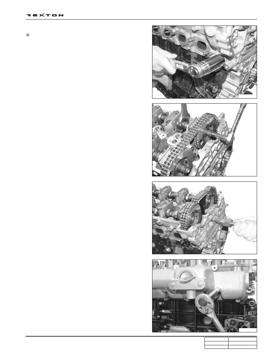
5. Hold the camshafts and remove the intake camshaft

sprocket and exhaust camshaft sprocket.

4. Remove the chain tensioner.

Preceding work: removal of EGR pipe and oil dipstick tube

6. Pull out the lock pins with a sliding hammer and remove

the upper guide rail.

7. Remove the oil cooler, then remove the intake manifold.

• The intake manifold can be interfered by the cylinder

head bolt (M8 x 50).

Y220_02015

Y220_02014

Y220_02013

Y220_02012

Notice

Correctly align the electronic control module onto
the shift plate by using two central pins when
installing.

DI02-8

CHANGED BY

EFFECTIVE DATE

AFFECTED VIN

ENGINE HOUSING

DI ENG SM - 2004.4

10. Remove the cylinder head.

11. Measure the piston protrusion from the parting surface.

• Specified Value: 0.765 ~ 1.055 mm

9. Measure the length of cylinder head bolts.

• If the maximum length is exceeded by 2 mm, replace

the cylinder head bolt.

8. Remove the cylinder head bolts according to the

numerical sequence.

M8 x 25

: 2 EA

M8 x 50

: 2 EA

M12 x 177 : 11 EA
M12 x 158 : 1 EA

(Vacuum pump side)

Y220_02016

Y220_02019

Y220_02018

Y220_02017

Notice

• Inspect the cylinder head surface.

• Store the removed injectors and glow plugs so that

they will not be damaged.

Length when new

177 mm

158 mm

Maximum Limit

179 mm

160 mm

DI02-9

CHANGED BY

EFFECTIVE DATE

AFFECTED VIN

ENGINE HOUSING

DI ENG SM - 2004.4

Y220_02020

Y220_02021

Y220_02022

Y220_02023

Reassembly

1. Install the cylinder head with the steel gasket.

2. Tighten the cylinder head bolts to specified torque and

torque angle.

3. Install the HLA device and finger follower. Check the HLA

device with the diagnosis procedures before installation.

4. Tighten the camshaft bearing cap bolts.

• Intake: #2, #4, #5

• Exhaust: #8, #10, #11

Notice

• Put the cylinder head on the locating pins.

Notice

• Apply the oil on the bolt thread when installing.

• Always insert new washer first.

• The bolts (12) at vacuum pump side are shorter than

others.

Notice

Make sure to place the “TOP” mark upward.

Tightening torque

Step 1 20 ± 2.0 Nm

Step 2 85 ± 5.0 Nm

Step 3 270° (90° x 3) + 10°

DI02-10

CHANGED BY

EFFECTIVE DATE

AFFECTED VIN

ENGINE HOUSING

DI ENG SM - 2004.4

• Exhaust: #1, #3, #6

• Intake: #7, #9, #12

Tightening torque

25 Nm

5. Install the intake and exhaust camshaft sprockets and

the timing chain.

Tightening torque

25 Nm + 90°

6. Rotate the crankshaft pulley two revolutions and ensure

that the OT mark on the crankshaft pulley and the OT
mark on the camshaft pulley are aligned.

7. Place the bearing cap with the OT marks on both

camshafts facing upward.

Y220_02024

Y220_02025

Y220_02026

Y220_02027

Notice

Check the finger follower positions and align if
needed.

Notice

• If the sprocket bolt is stretched over 0.9 mm, replace

it with new one.

• Always install the intake camshaft sprocket first.
• Ensure that the markings on camshaft sprocket and

timing chain are aligned.

• Make sure that the timing chain is securely seated

on the guide rail.

Notice

If the markings are not aligned, reinstall the cylinder
head.

Notice

• Apply the sealant on the cap (#12) for the vacuum

pump when installing.

• Apply the oil on the bearing journals before

installation.

Intake

Exhaust


Content   ..  27  28  29  30   ..