Renault Megane Sport Tourer (2016 year). Manual - part 14
5.19
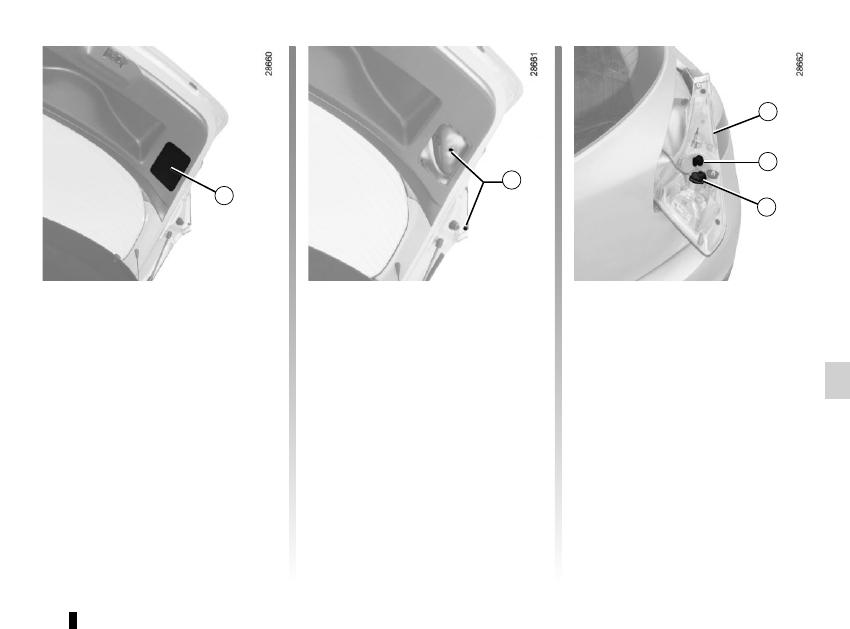
REAR LIGHTS AND INDICATOR LIGHTS: changing bulbs
(2/6)
Five-door versions
(continued)
Fog lights/side lights and reversing
lights
– From the luggage compartment,
unclip flap 7, then remove the
bolts 8.
– Lower the tailgate, then pull light 9
towards the rear to release it.
– Unscrew the bulb holder for the bulb
concerned.
7
9
10
8
11
Reversing light 10
Bulb type: W16W.
Fog light (left or right-hand side)/
side light 11
Bulb type: P21/4W.