Renault Megane Sport Tourer (2016 year). Manual - part 13
5.3
TYRE INFLATION KIT
(1/5)
The kit is only approved for
inflating the tyres of the ve-
hicle originally equipped
with the kit.
It must never be used to inflate
the tyres of another vehicle, or any
other inflatable object (rubber ring,
rubber boat, etc.).
Avoid spillage on skin when han-
dling the repair liquid bottle. If drop-
lets do leak out, rinse them off with
plenty of water.
Keep the repair kit away from chil-
dren.
Do not dispose of the empty bottle
in the countryside. Return it to your
approved dealer or to a recycling or-
ganisation.
The bottle has a limited service
life which is indicated on its label.
Check the expiry date.
Contact an approved dealer to re-
place the inflation tube and repair
product bottle.
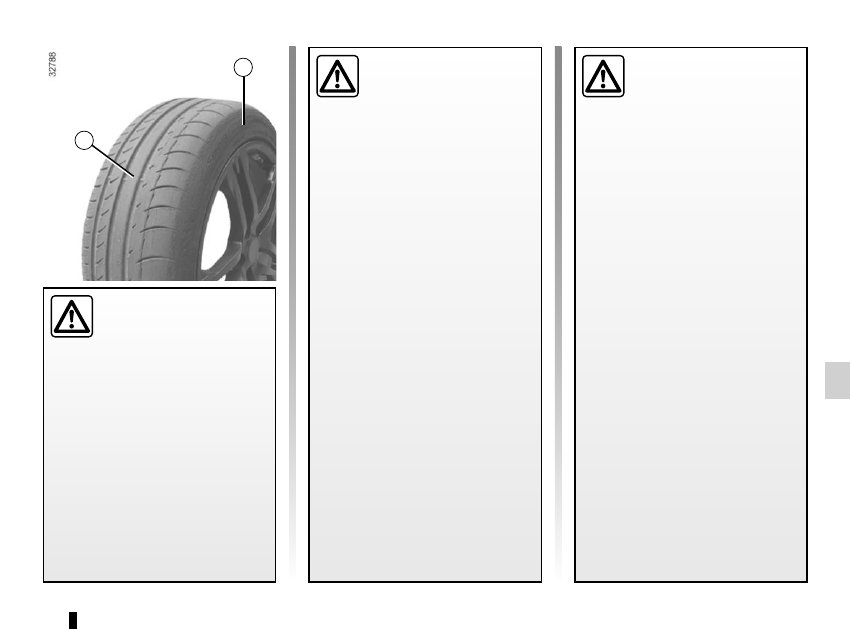
A
B
The kit repairs tyres when
tread A has been dam-
aged by objects smaller
than 4 mm. It cannot repair
all types of puncture, such as cuts
larger than 4 mm, or cuts in tyre
sidewall B.
Ensure also that the wheel rim is in
good condition.
Do not pull out the foreign body
causing the puncture if it is still in
the tyre.
Do not attempt to use the
inflation kit if the tyre has
been damaged as a result
of driving with a puncture.
You should therefore carefully check
the condition of the tyre sidewalls
before any operation.
Driving with underinflated, flat or
punctured tyres can be dangerous
and may make the tyre impossible
to repair.
This repair is temporary
A tyre which has been punctured
should always be inspected (and re-
paired, where possible) as soon as
possible by a specialist.
When taking a tyre which has been
repaired using this kit to be replaced,
you must inform the specialist.
When driving, vibration may be felt
due to the presence of the repair
product injected into the tyre.