Peugeot 4007 (2012 year). Manual - part 9
8
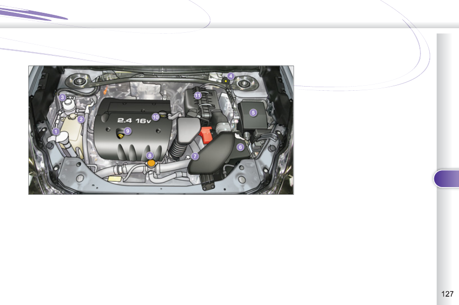
CHECKS
PETROL ENGINE
1. Screenwash and headlamp wash
reservoir.
2. Coolant reservoir.
3. Power steering fl uid reservoir.
4. Brake fl uid reservoir.
5. Fusebox.
6. Battery.
7. CVT gearbox dipstick.
8. Radiator cap.
9. Engine oil dipstick.
10. Engine oil fi ller cap.
11. Air fi lter.
Access for checking the levels of the various fl uids and the replacement of certain components.