Nissan Titan (2019 year). Manual - part 15


  Index      Nissan     Nissan Titan - service manual 2019 year in english


Search            copyright infringement  


Content   ..  13  14  15  16   ..


Nissan Titan (2019 year). Manual - part 15


For additional information, refer to the
“HomeLink® Universal Transceiver” in the
“Instruments and controls” section of this
manual.

OUTSIDE MIRRORS

WARNING

∙ Objects viewed in the outside mirror

on the passenger side are closer than
they appear. Be careful when moving
to the right. Using only this mirror
could cause an accident. Use the in-
side mirror or glance over your shoul-
der to properly judge distances to
other objects.

∙ Do not adjust the mirrors while driv-

ing. You could lose control of your ve-
hicle and cause an accident.

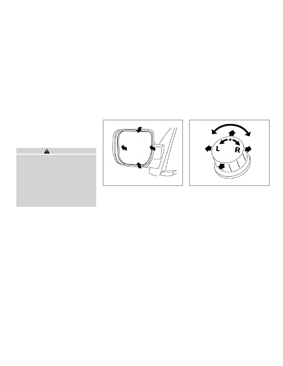
Manual control type (if so
equipped)

The outside mirrors can be moved in any
direction for a better rear view.

Electric control type (if so
equipped)

The outside mirror remote control will op-
erate only when the ignition switch is
placed in the ACC or ON position.

Rotate the control dial to select the right or
left mirror. Adjust the mirror to the desired
position by moving the control dial.

Return the control dial to the center (neu-
tral) position to prevent accidentally mov-
ing the mirror.

LPD2581

LPD2606

Pre-driving checks and adjustments

3-35

Trailer tow mirrors (if so equipped)

WARNING

Objects viewed in the convex portion of
the trailer tow mirror are closer than
they appear. Be careful when changing
lanes or turning. Using only the convex
mirror could cause an accident. Use the
other mirrors or glance over your shoul-
der to properly judge distances to other
objects.

Use the outside mirror remote control to
adjust the top portion of the trailer tow
mirror.

The lower portion of the trailer tow mirror
can be moved manually in any direction for
a better rear view.

Pull the trailer tow mirror outward to ex-
tend it to the desired position for better
visibility while towing a trailer.

WARNING

Do not extend or retract mirrors while
driving. You may lose control of your ve-
hicle and cause an accident.

CAUTION

Driving in tight spaces with mirrors ex-
tended may cause damage to the
vehicle.

LPD2474

LPD0268

3-36

Pre-driving checks and adjustments

Power folding outside mirrors (if
so equipped)

CAUTION

Do not manually fold the power folding
mirrors. Manually folding the mirrors
can damage the mirrors.

Push the switch to open or close the mir-
rors.

If one of the mirrors are manually operated
or bumped, the mirror body can become
loose at the pivot point. To correct elec-
tronic mirror operation, cycle the mirrors by
pushing the “CLOSE” switch until com-
pletely closed, then push the “OPEN” switch
until the mirrors are in the open position.

Manual folding outside mirrors (if
so equipped)

Pull the outside mirror toward the door to
fold it.

Reverse tilt-down feature (if so
equipped)

The reverse tilt-down feature will turn both
outside mirror surfaces downward to pro-
vide better rear visibility close to the vehicle
when the mirror control switch is in either
the L or R position.

LPD0417

Type A (if so equipped)

LPD2634

Pre-driving checks and adjustments

3-37

The mirrors automatically return to their
original position when you shift out of R
(Reverse).

The outside mirror surfaces will return to
their original position when one of the fol-
lowing conditions has occurred:

∙ The shift lever is moved to any position

other than R (Reverse).

∙ The outside mirror control switch is set

to the neutral or center position.

∙ The ignition switch is placed in the OFF

position.

NOTE:

If the outside mirror control switch is in
the center position, the mirror surface
will NOT turn downward when the shift
lever is moved to R (Reverse).

For additional information, refer to “Auto-
matic drive positioner” in this section.

Automatic anti-glare outside
mirror (if so equipped)

The outside mirror will automatically dim
during nighttime conditions to reduce the
glare from the headlights of trailing ve-
hicles. The automatic anti-glare feature
operates only when the ignition switch is
placed in the ON position.

The automatic anti-glare feature will be on
when starting the vehicle. The indicator
light on the automatic anti-glare rearview
mirror will illuminate when the automatic
anti-glare feature is operating.

To turn off the anti-glare feature, press
the

button on the rearview mirror.

The indicator light will turn off.
To turn on the anti-glare feature again,
press the

button on the rearview mir-

ror. The indicator light will turn on.

For additional information on the auto-
matic anti-glare rearview mirror, refer to
“Automatic anti-glare rearview mirror” in
this section.

Heated mirrors (if so equipped)

Some outside mirrors can be heated to
defrost, defog, or de-ice for improved vis-
ibility. For additional information, refer to
“Rear window and/or outside mirror de-
froster switch” in the “Instruments and con-
trols” section of this manual.

Type B (if so equipped)

LPD0269

3-38

Pre-driving checks and adjustments

TAILGATE

Opening the tailgate

Pull the tailgate handle upward and lower
the tailgate. The support cables hold the
tailgate open.

When closing the tailgate, make sure the
latches are securely locked.

Do not drive the vehicle with the tailgate
down, unless equipped with NISSAN’s
Bed Extender (accessory) or equivalent
in the extended position.

For additional information on proper truck
box loading, refer to “Vehicle loading infor-
mation” in the “Technical and consumer in-
formation” section of this manual.

WARNING

∙ Never allow anyone to ride in the

cargo area or on the rear seat (if so
equipped) when it is in the folded po-
sition. Use of these areas by passen-
gers without proper restraints could
result in serious injury or death in an
accident or sudden stop.

∙ It is extremely dangerous to ride in a

cargo area inside a vehicle. In a colli-
sion, people riding in these areas are
more likely to be seriously injured or
killed.

∙ Do not allow people to ride in any area

of your vehicle that is not equipped
with seats and seat belts.

∙ Be sure everyone in your vehicle is in a

seat and using a seat belt properly.

LPD2334

TRUCK BOX

Pre-driving checks and adjustments

3-39

Disconnecting the rear camera

Before removing the tailgate disconnect
the rear camera by performing the follow-
ing:

1. Open the tailgate to access the rear

camera connector bracket

1

located

on the rear sill.

2. Remove the connector bracket

2

from the sill by pressing the locking tab
inward, in the direction shown, while
pulling the bracket apart.

3. Disconnect the chassis wiring harness

3

by pressing inward on the locking

tab, in the direction shown, while pulling
the connectors apart. Hold the con-
nector firmly to prevent the connector
in the chassis harness from falling into
the sill.

4. Use the supplied chassis plug and

bracket and connect them to the
chassis wiring harness to avoid con-
tamination to the terminals which will
lead to malfunction of the rear camera.

5. Insert the bracket back into the sill.

6. Take the tailgate plug from the glove

box and connect it to the tailgate wir-
ing harness to avoid contamination
which will lead to malfunction of the
rear camera.

7. Remove the tailgate. For additional in-

formation, refer to “Removing the tail-
gate” in this section.

LPD2582

3-40

Pre-driving checks and adjustments

Removing the tailgate

1. Disconnect the wiring harness for the

rear camera (if so equipped). For addi-
tional information, refer to “Disconnect-
ing the rear camera” in this section.

2. Release the tailgate support cables.

CAUTION

∙ The tailgate is heavy. Two people

should remove or install it. Be careful
not to drop it during removal.

∙ After releasing the support cables, do

not let the tailgate rest on the
bumper.

3. Hold the tailgate at a 45 degree angle.

4. Pull the tailgate out from the left side

hinge.

5. Slide the tailgate out of the right side

hinge.

Installing the tailgate

1. Insert the tailgate into the right side

hinge.

2. Hold the tailgate at a 45 degree angle

and insert into the left side hinge.

3. Continue to hold the tailgate at a 45

degree angle and attach the tailgate
support cables.

4. For vehicles with rear camera: Be sure

the tailgate harness is not hanging be-
low the tailgate and keep the tailgate
open. For additional information, refer
to “Connecting the rear camera” in this
section before closing the tailgate.

5. For vehicles without rear camera: Close

the tailgate securely.

LPD0271

Pre-driving checks and adjustments

3-41

Connecting the rear camera

Before closing the tailgate reconnect the
rear camera by performing the following:

1. After attaching the rear tailgate to the

truck, keep the tailgate open and check
that the tailgate harness is not hanging
below the tailgate.

2. Remove the connector bracket

2

from the sill by pressing the locking tab
inward, in the direction shown, while
pulling the bracket apart.

3. Disconnect

the

chassis

plug

and

bracket from the chassis wiring har-

ness

3

. Keep the connector and

bracket in a safe place such as the
glove box.

4. Disconnect the tailgate plug from the

tailgate wiring harness. Keep the tail-
gate plug in a safe place such as the
glove box.

5. Connect the tailgate wiring harness to

the chassis wiring harness.

6. Securely fix the rear camera connector

bracket

1

to the rear sill.

7. Close the tailgate securely.

Locking the Tailgate

To unlock the tailgate, turn the key toward
the passenger side of the vehicle

1

. To

lock, turn the key toward the driver side

2

.

If your vehicle is equipped with an elec-
tronic tailgate, you may use the door
handle request switch (if so equipped) or
I-key to lock or unlock the tailgate. For ad-
ditional information please refer to “NISSAN
Intelligent Key® Operation” in the this sec-
tion of the manual.

LPD2582

3-42

Pre-driving checks and adjustments

TIE DOWN HOOKS

For your convenience, tie down hooks are
placed at each corner of the truck box.
These may be used to help secure cargo
loaded into the truck box.

∙ The weight of the cargo load must be

evenly distributed over the rear axles.

∙ All cargo should be securely fastened

with ropes or straps to prevent it from
shifting or sliding within the vehicle.

WARNING

∙ Properly secure all cargo with ropes or

straps to help prevent it from sliding
or shifting. In a sudden stop or colli-
sion, unsecured cargo could cause
personal injury.

The automatic drive positioner system has
two features:

∙ Memory storage function

∙ Entry/exit function

LPD2393

AUTOMATIC DRIVE POSITIONER (if so
equipped)

Pre-driving checks and adjustments

3-43

MEMORY STORAGE FUNCTION

Two positions for the driver’s seat, steering
column,

and

outside

mirrors

(if

so

equipped) can be stored in the automatic
drive positioner memory. Follow these pro-
cedures to set the memory system.

1. Place the ignition in the ON or ACC po-

sition (the vehicle should be stopped
while setting the memory).

2. Adjust the driver’s seat, steering col-

umn,

and

outside

mirrors

(if

so

equipped) to the desired positions by
manually operating each adjusting
switch. For additional information, refer

to “Seats” in the “Safety—Seats, seat
belts and supplemental restraint sys-
tem” section of this manual, and “Steer-
ing wheel” and “Outside mirrors” in this
section.

3. Push the SET switch and, within 5 sec-

onds, push the memory switch (1 or 2).

4. The indicator light for the pushed

memory switch will come on and stay
on for approximately 5 seconds.

5. The

chime

will

sound

when

the

memory is stored.

NOTE:

If a NEW memory position is stored in the
same memory switch, the previous
memory position will be overwritten by
the new stored position.

Confirming memory storage

∙ Push the SET switch.

∙ If a memory position has been stored in

the switch (1 or 2) then the indicator light
for the respective switch will stay on for
approximately 5 seconds.

Linking a key fob to a stored
memory position

Each key fob can be linked to a stored
memory position (memory switch 1 or 2)
with the following procedure.

1. Follow steps 1-3 in the “Memory storage

function”

section

for

storing

the

memory position.

2. The indicator light for the pushed

memory switch will come on. While the
indicator light is on for 5 seconds, press
the

button on the key fob. The

hazard lights will flash twice. The indi-
cator light of the linked memory switch
will blink and click twice. After the indi-
cator light goes off, the key fob is linked
to that memory setting.

Once it is linked, when the ignition switch is
in the OFF position, pressing the

but-

ton on the key fob will move the driver’s
seat, steering wheel and outside mirrors to
the linked memory switch position.

NOTE:

If a new memory position is stored in the
linked memory switch, then the key fob
will link the new position and overwrites
the previous position.

LPD2302

3-44

Pre-driving checks and adjustments

ENTRY/EXIT FUNCTION

This system is designed so that the driver’s
seat and steering column will automati-
cally move when the shift lever is in the P
(Park) position. This allows the driver to
easily get in and out of the driver’s seat.

The driver’s seat will slide backward and
the steering column will move up:

∙ When the driver’s door is opened with

the ignition switch in the OFF position.

∙ When the ignition switch is changed

from ACC to OFF with the driver’s door
open.

The driver’s seat and steering wheel will
return to the previous position:

∙ When the ignition switch is changed

from ACC or ON while the shift lever is in
the P (Park) position.

The entry/exit function can be adjusted or
canceled through the vehicle settings in
the vehicle information display by perform-
ing the following:

∙ Switch the Exit Seat Slide from ON to

OFF.

∙ Switch the Exit Steering UP from ON to

OFF.

Restarting the entry/exit function

If the battery cable is disconnected, or if the
fuse opens, the stored memory positions
will be lost and some of the functions will
be restricted:

1. Drive the vehicle over 25 mph (40 km/h).

OR

2. Open and close the driver’s door more

than two times with the ignition switch
in the OFF position.

The entry/exit function should now work
properly.

SYSTEM OPERATION

The automatic drive positioner system will
not work or will stop operating under the
following conditions:

∙ When the vehicle speed is above 4 mph

(7 km/h).

∙ When any of the memory switches are

pushed while the automatic drive posi-
tioner is operating.

∙ When the switch for the driver’s seat

and steering column is pushed while
the automatic drive positioner is oper-
ating.

∙ When the seat has already been moved

to the memorized position.

∙ When no seat position is stored in the

memory switch.

∙ When the shift lever is moved from P

(Park) to any other position.

Pre-driving checks and adjustments

3-45

4 Monitor, climate, audio, phone and
voice recognition systems

NissanConnect® Owner’s Manual . . . . . . . . . . . . . . . . 4-2
RearView Monitor (if so equipped) . . . . . . . . . . . . . . . 4-3

RearView Monitor system operation . . . . . . . . . . 4-4
How to read the displayed lines. . . . . . . . . . . . . . . 4-5
Difference between predicted and
actual distances. . . . . . . . . . . . . . . . . . . . . . . . . . . . . . 4-5
How to park with predicted course
lines . . . . . . . . . . . . . . . . . . . . . . . . . . . . . . . . . . . . . . . . . . 4-7
Adjusting the screen . . . . . . . . . . . . . . . . . . . . . . . . . 4-8
How to turn on and off predicted
course lines . . . . . . . . . . . . . . . . . . . . . . . . . . . . . . . . . . 4-9
RearView Monitor system limitations . . . . . . . . . 4-9
System maintenance. . . . . . . . . . . . . . . . . . . . . . . . 4-10

Intelligent Around View Monitor
(if so equipped) . . . . . . . . . . . . . . . . . . . . . . . . . . . . . . . . . .4-11

Intelligent Around View Monitor system
operation. . . . . . . . . . . . . . . . . . . . . . . . . . . . . . . . . . . . 4-12
Difference between predicted and
actual distances. . . . . . . . . . . . . . . . . . . . . . . . . . . . . 4-16
How to park with predicted course
lines . . . . . . . . . . . . . . . . . . . . . . . . . . . . . . . . . . . . . . . . . 4-18
How to switch the display . . . . . . . . . . . . . . . . . . . 4-19
Adjusting the screen . . . . . . . . . . . . . . . . . . . . . . . . 4-20

Intelligent Around View Monitor system
limitations . . . . . . . . . . . . . . . . . . . . . . . . . . . . . . . . . . . 4-21
System maintenance. . . . . . . . . . . . . . . . . . . . . . . . 4-23

Moving Object Detection (MOD)
(if so equipped) . . . . . . . . . . . . . . . . . . . . . . . . . . . . . . . . . 4-24

MOD system operation . . . . . . . . . . . . . . . . . . . . . . 4-25
Turning MOD on and off (if so equipped) . . . . . 4-27
MOD system limitations . . . . . . . . . . . . . . . . . . . . . 4-27
System maintenance. . . . . . . . . . . . . . . . . . . . . . . . 4-28

Vents. . . . . . . . . . . . . . . . . . . . . . . . . . . . . . . . . . . . . . . . . . . 4-29
Heater and air conditioner (manual)
(if so equipped) . . . . . . . . . . . . . . . . . . . . . . . . . . . . . . . . . 4-29

Controls . . . . . . . . . . . . . . . . . . . . . . . . . . . . . . . . . . . . . 4-30
Heater operation . . . . . . . . . . . . . . . . . . . . . . . . . . . . 4-31
Air conditioner operation . . . . . . . . . . . . . . . . . . . . 4-33
Air flow charts . . . . . . . . . . . . . . . . . . . . . . . . . . . . . . . 4-34

Heater and air conditioner (automatic)
(if so equipped) . . . . . . . . . . . . . . . . . . . . . . . . . . . . . . . . . 4-38

Automatic operation . . . . . . . . . . . . . . . . . . . . . . . . 4-39
Manual operation . . . . . . . . . . . . . . . . . . . . . . . . . . . 4-40
Operating tips . . . . . . . . . . . . . . . . . . . . . . . . . . . . . . . 4-42

Servicing air conditioner . . . . . . . . . . . . . . . . . . . . . . . . 4-43
USB/iPod® charging port . . . . . . . . . . . . . . . . . . . . . . . 4-43

Antenna . . . . . . . . . . . . . . . . . . . . . . . . . . . . . . . . . . . . . . . . 4-44
Rear Seat Infotainment (RSI) (if so equipped) . . . . 4-44

Welcome . . . . . . . . . . . . . . . . . . . . . . . . . . . . . . . . . . . . 4-45
Getting started . . . . . . . . . . . . . . . . . . . . . . . . . . . . . . 4-45
Control description . . . . . . . . . . . . . . . . . . . . . . . . . . 4-51
Remote control operation . . . . . . . . . . . . . . . . . . . 4-52
Remote control buttons . . . . . . . . . . . . . . . . . . . . . 4-53
Wireless headphone operation . . . . . . . . . . . . . . 4-54
General operation . . . . . . . . . . . . . . . . . . . . . . . . . . . 4-55
DVD operation. . . . . . . . . . . . . . . . . . . . . . . . . . . . . . . 4-57
DVD playback controls . . . . . . . . . . . . . . . . . . . . . . 4-58
CD operation . . . . . . . . . . . . . . . . . . . . . . . . . . . . . . . . 4-61
CD playback controls . . . . . . . . . . . . . . . . . . . . . . . . 4-62

HDMI/MHL connection . . . . . . . . . . . . . . . . . . . . . . 4-62
USB/SD card operation . . . . . . . . . . . . . . . . . . . . . . 4-64
Slingplayer® . . . . . . . . . . . . . . . . . . . . . . . . . . . . . . . . . 4-69
Miracast®. . . . . . . . . . . . . . . . . . . . . . . . . . . . . . . . . . . . 4-72
Using the mobile application on your
mobile device . . . . . . . . . . . . . . . . . . . . . . . . . . . . . . . 4-72
SmartStream. . . . . . . . . . . . . . . . . . . . . . . . . . . . . . . . 4-73
Settings . . . . . . . . . . . . . . . . . . . . . . . . . . . . . . . . . . . . . 4-74
Troubleshooting . . . . . . . . . . . . . . . . . . . . . . . . . . . . . 4-82
Specifications . . . . . . . . . . . . . . . . . . . . . . . . . . . . . . . 4-85
Compliance information. . . . . . . . . . . . . . . . . . . . .4-86

Car phone or CB radio . . . . . . . . . . . . . . . . . . . . . . . . . .4-89

Refer to the NissanConnect® Owner’s
Manual that includes the following infor-
mation.

∙ NissanConnect®

Services

(if

so

equipped)

∙ Navigation system (if so equipped)

∙ Audio system

∙ Apple CarPlay

TM

∙ Android Auto

TM

∙ Bluetooth® Hands-Free Phone system

∙ Viewing information

∙ Other settings

∙ Voice recognition

∙ General system information

NISSANCONNECT® OWNER’S
MANUAL

4-2

Monitor, climate, audio, phone and voice recognition systems

1. CAMERA button

LHA4859

REARVIEW MONITOR (if so
equipped)

Monitor, climate, audio, phone and voice recognition systems

4-3

WARNING

∙ Failure to follow the warnings and in-

structions for proper use of the Rear-
View Monitor system could result in
serious injury or death.

∙ RearView Monitor is a convenience

feature and is not a substitute for
proper backing. Always turn and look
out the windows and check mirrors to
be sure that it is safe to move before
operating the vehicle. Always back up
slowly.

∙ The system is designed as an aid to

the driver in showing large stationary
objects directly behind the vehicle, to
help avoid damaging the vehicle.

∙ The distance guide line and the ve-

hicle width line should be used as a
reference only when the vehicle is on a
level paved surface. The distance
viewed on the monitor is for reference
only and may be different than the
actual distance between the vehicle
and displayed objects.

CAUTION

Do not scratch the camera lens when
cleaning dirt or snow from the front of
the camera.

The RearView Monitor system automati-
cally shows a rear view of the vehicle when
the shift lever is shifted into the R (Reverse)
position. While in R (Reverse), pressing the
CAMERA will cycle through guideline op-
tions. The radio can still be heard while the
RearView Monitor is active.

To display the rear view, the RearView Moni-
tor system uses a camera located just
above the vehicle’s license plate

1

on the

tailgate.

REARVIEW MONITOR SYSTEM
OPERATION

With the ignition switch in the ON position,
move the shift lever to the R (Reverse) po-
sition to operate the RearView Monitor.

LHA3671

4-4

Monitor, climate, audio, phone and voice recognition systems


Content   ..  13  14  15  16   ..