Nissan Versa Note. Instruction - part 396


  Index      Nissan     Nissan Versa Note (2014 year) - Service and Repair Instruction


Search            copyright infringement  


Content   ..  394  395  396  397   ..


Nissan Versa Note. Instruction - part 396


EM-100

< UNIT DISASSEMBLY AND ASSEMBLY >

[HR16DE]

CYLINDER BLOCK

Install the rear oil seal after installing the oil pan (upper).

17. Install rear oil seal. Refer to 

EM-74, "REAR OIL SEAL : Removal and Installation"

.

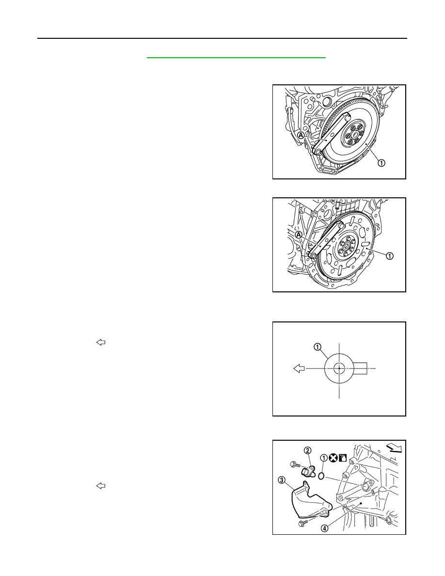
18. Install flywheel (M/T models) or drive plate (CVT models).

M/T models

• Secure crankshaft with a stopper plate (A) and tighten bolts

crosswise over several times.

CVT models

• Secure crankshaft with a stopper plate (A) and tighten bolts

crosswise over several times.

CAUTION:

Do not damage or scratch and contact surface for clutch disc of flywheel.

19. Install knock sensor (1).

• Install connectors so that they are positioned toward the rear

of the engine.

CAUTION:

• Do not tighten bolt while holding the connector.   

• If any impact by dropping is applied to knock sensor,

replace it with a new one.

NOTE:

• Check that there is no foreign material on the cylinder block

mating surface and the back surface of knock sensor. 

• Check that knock sensor does not interfere with other parts.

20. Install crankshaft position sensor (POS) (2) and O-ring (1) and

then install the crankshaft position sensor cover (3) on the cylin-

der block (4).

• Tighten bolts with sensor inserted completely.

CAUTION:

• Avoid impacts such as a dropping.

• Do not disassemble.

• Keep sensor away from metal particles.

• Do not place the sensor in a location where it is exposed

to magnetism.

• Do not reuse O-ring.

(1) :Flywheel

Tool number

: KV11105210 (J-44716)

MBIB1382E

(1) :Drive plate

Tool number

: KV11105210 (J-44716)

PBIC3226J

: Engine front

: Engine front

PBIC3754E

JPBIA4202ZZ

CYLINDER BLOCK

EM-101

< UNIT DISASSEMBLY AND ASSEMBLY >

[HR16DE]

C

D

E

F

G

H

I

J

K

L

M

A

EM

N

P

O

21. For the oil level gauge guide (1), secure in position (B) shown to

the water inlet clip (A) after inserting to the cylinder block side.

22. Assembly of the remaining components is in the reverse order of disassembly. 

Inspection

INFOID:0000000009444755

CRANKSHAFT END PLAY

• Measure the clearance between thrust bearings and crankshaft

arm when crankshaft is moved fully forward or backward using

suitable tool (A).

• If the measured value exceeds the limit, replace thrust bearings,

and measure again. If it still exceeds the limit, replace crankshaft

also.

CONNECTING ROD SIDE CLEARANCE

• Measure the side clearance between connecting rod and crank-

shaft arm using suitable tool (A).

• If the measured value exceeds the limit, replace connecting rod,

and measure again. If it still exceeds the limit, replace crankshaft

also.

PISTON TO PISTON PIN OIL CLEARANCE

Piston Pin Hole Diameter 

Measure the inner diameter of piston pin hole using suitable tool (A).

Piston Pin Outer Diameter 

PBIC3755E

Standard and Limit

: Refer to 

EM-120, "Cylinder 

Block"

.

PBIC3762E

Standard and Limit : Refer to 

EM-120, "Cylinder 

Block"

.

PBIC3763E

Standard

: Refer to 

EM-120, "Cylinder Block"

.

PBIC3265J

EM-102

< UNIT DISASSEMBLY AND ASSEMBLY >

[HR16DE]

CYLINDER BLOCK

Measure the outer diameter of piston pin using suitable tool (A).

Piston to Piston Pin Oil Clearance

(Piston to piston pin oil clearance) = (Piston pin hole diameter) – (Piston pin outer diameter)

• If oil clearance is out of the standard, replace piston and piston pin assembly. 

• When replacing piston and piston pin assembly. Refer to 

EM-93, "Disassembly and Assembly"

.

NOTE:

• Piston is available together with piston pin as assembly.

• Piston pin (piston pin hole) grade is provided only for the parts installed at the factory. For service parts, no

grades can be selected. Only grade “0” is available. 

PISTON RING SIDE CLEARANCE

• Measure the side clearance of piston ring and piston ring groove

with a suitable tool (A).

• If the measured value exceeds the limit, replace piston ring, and

measure again. If it still exceeds the limit, replace piston also.

PISTON RING END GAP

• Check that cylinder bore inner diameter is within specification. Refer to “PISTON TO CYLINDER BORE

CLEARANCE”.

• Lubricate piston (1) and piston ring (2) with new engine oil and

then insert (A) piston ring until middle of cylinder (B) with piston,

and measure piston ring end gap using feeler gauge (C).

• If the measured value exceeds the limit, replace piston ring, and

measure again. If it still exceeds the limit, replace cylinder block.

CONNECTING ROD BEND AND TORSION

Standard : 

Refer 

to 

EM-120, "Cylinder Block"

.

PBIC3266J

Standard : 

Refer 

to 

EM-120, "Cylinder Block"

.

Standard and Limit

: Refer to 

EM-120, "Cylinder 

Block"

.

PBIC3280J

Standard and Limit

: Refer to 

EM-120, "Cylinder 

Block"

.

PBIC3267J

CYLINDER BLOCK

EM-103

< UNIT DISASSEMBLY AND ASSEMBLY >

[HR16DE]

C

D

E

F

G

H

I

J

K

L

M

A

EM

N

P

O

• Check using connecting rod aligner.

• If it exceeds the limit, replace connecting rod assembly.

CONNECTING ROD BIG END DIAMETER

• Install connecting rod cap (1) without connecting rod bearing

installed, and tightening connecting rod cap bolts to the specified

torque. Refer to 

EM-92, "Exploded View"

.

• Measure the inner diameter (B) of connecting rod big end using

suitable tool.

• If out of the standard, replace connecting rod assembly.

CONNECTING ROD BUSHING OIL CLEARANCE

Connecting Rod Bushing Inner Diameter

Measure the inner diameter of connecting rod bushing using suitable

tool (A).

Piston Pin Outer Diameter

(A)

: Bend

(B)

: Torsion

(C)

: Feeler gauge

Limit

: Refer to 

EM-120, "Cylinder Block"

.

PBIC3268J

(2)

: Connecting rod

(A)

: Example

(B)

: Measuring direction of inner diameter

Standard : 

Refer 

to 

EM-120, "Cylinder Block"

.

PBIC3269J

Inner diameter 
(Standard) 

: Refer to 

EM-120, "Cylinder 

Block"

.

JPBIA0223ZZ


Content   ..  394  395  396  397   ..