Nissan Versa Note. Instruction - part 394
EM-92
< UNIT DISASSEMBLY AND ASSEMBLY >
[HR16DE]
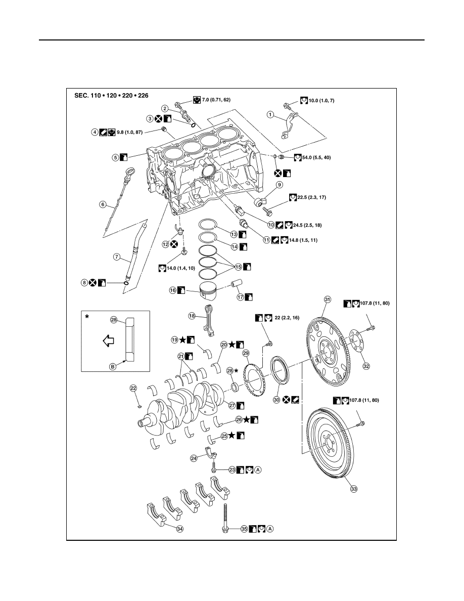
CYLINDER BLOCK
CYLINDER BLOCK
Exploded View
INFOID:0000000009444753
1.
Crankshaft position sensor cover
2.
Crankshaft position sensor (POS)
3.
O-ring
4.
Drain plug
5.
Cylinder block
6.
Oil level gauge
7.
Oil level gauge guide
8.
O-ring
9.
Knock sensor
AWBIA1621ZZ