Nissan Versa Sedan. Instruction - part 883


  Index      Nissan     Nissan Versa Sedan (2014 year) - Service and Repair Instruction


Search            copyright infringement  


Content   ..  881  882  883  884   ..


Nissan Versa Sedan. Instruction - part 883


TM-438

< REMOVAL AND INSTALLATION >

[CVT: RE0F11A]

AIR BREATHER HOSE

AIR BREATHER HOSE

Removal and Installation

INFOID:0000000009268254

REMOVAL

1. Remove air duct (inlet). Refer to 

EM-25, "Exploded View"

.

2. Remove air breather hose from transaxle assembly.

INSTALLATION

Installation is in the reverse order of removal.

CAUTION:

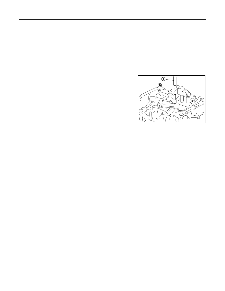
• Check that air breather hose is not collapsed or blocked due to folding or bending when installed.

• Be sure to insert air breather hose (1) fully until it reaches the

base of the transaxle tube (A).

JSDIA1978ZZ

G SENSOR

TM-439

< REMOVAL AND INSTALLATION >

[CVT: RE0F11A]

C

E

F

G

H

I

J

K

L

M

A

B

TM

N

O

P

G SENSOR

Exploded View

INFOID:0000000009268255

Removal and Installation

INFOID:0000000009268256

CAUTION:

• Do not drop or strike G sensor, because it may be damaged by impact.

• Do not use a power tool.

REMOVAL

1. Disconnect the battery negative terminal. Refer to 

PG-63, "Removal and Installation"

.

2. Remove center console. Refer to 

IP-23, "Removal and Installation"

.

3. Disconnect the harness connector from G sensor.
4. Remove G sensor.

INSTALLATION

Installation is in the reverse order of removal.

Adjustment

INFOID:0000000009268257

ADJUSTMENT AFTER INSTALLATION

Perform “G SENSOR CALIBRATION”. Refer to 

TM-328, "Description"

.

1.

G sensor

Front

JSDIA1922GB

TM-440

< REMOVAL AND INSTALLATION >

[CVT: RE0F11A]

OIL PAN

OIL PAN

Exploded View

INFOID:0000000009268258

Removal and Installation

INFOID:0000000009268259

REMOVAL

1. Remove the drain plug and overflow tube, and then drain the CVT fluid.

WARNING:

CVT fluid can splash when draining, use safety glasses to protect eyes.

2. Remove the drain plug gasket from the drain plug.
3. Remove the oil pan bolts (

), and then remove the oil pan and

oil pan gasket.

4. Remove the magnets from the oil pan.

INSTALLATION

Installation is in the reverse order of removal.

CAUTION:

• Do not reuse oil pan gasket and drain plug gasket.

1.

Transaxle assembly

2.

Oil pan gasket

3.

Magnet

4.

Oil pan

5.

Overflow tube

6.

Drain plug gasket

7.

Drain plug

8.

Oil pan fitting bolt

JSDIA1879GB

: Front

JSDIA1874ZZ

OIL PAN

TM-441

< REMOVAL AND INSTALLATION >

[CVT: RE0F11A]

C

E

F

G

H

I

J

K

L

M

A

B

TM

N

O

P

• Do not reuse oil pan bolts.

• Completely remove all moisture, oil and old gasket, etc. from the oil pan gasket mating surface of

transaxle case and oil pan.

• When installing the overflow tube, be sure to tighten to the specified torque. If it is not tightened to

the specified torque, the tube may be damaged.

• When the oil pan is installed, temporarily tighten oil pan bolts, then

tighten the oil pan bolts to specification in the order shown.

Inspection and Adjustment

INFOID:0000000009268260

INSPECTION AFTER REMOVAL

Check oil pan for foreign material.

• If a large amount of worn material is found, clutch plate may be worn. 

• If iron powder is found, bearings, gears, or clutch plates may be worn.

• If aluminum powder is found, bushing may be worn, or chips or burrs of aluminum casting parts may enter.

Check points where wear is found in all cases.

INSPECTION AFTER INSTALLATION

Check for CVT fluid leakage. Refer to 

TM-426, "Inspection"

.

ADJUSTMENT AFTER INSTALLATION

Check the CVT fluid level. Refer to 

TM-427, "Adjustment"

.

: Front

JSDIA1884ZZ


Content   ..  881  882  883  884   ..