Nissan Versa Sedan. Instruction - part 882


  Index      Nissan     Nissan Versa Sedan (2014 year) - Service and Repair Instruction


Search            copyright infringement  


Content   ..  880  881  882  883   ..


Nissan Versa Sedan. Instruction - part 882


TM-434

< REMOVAL AND INSTALLATION >

[CVT: RE0F11A]

CONTROL CABLE

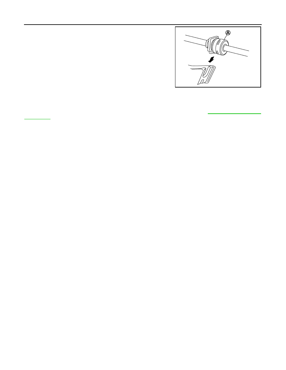
2. Install the socket (A) onto the CVT shift selector assembly.

CAUTION:

• Insert the socket into the CVT shift selector assembly,

then push it firmly in place.

• Check that pulling on the socket does not disconnect it.

Inspection

INFOID:0000000009268247

INSPECTION AFTER INSTALLATION

 Check the CVT position. If a malfunction is found, adjust the CVT position. Refer to 

TM-430, "Inspection and

Adjustment"

.

JSDIA1810ZZ

KEY INTERLOCK CABLE

TM-435

< REMOVAL AND INSTALLATION >

[CVT: RE0F11A]

C

E

F

G

H

I

J

K

L

M

A

B

TM

N

O

P

KEY INTERLOCK CABLE

Exploded View

INFOID:0000000009268248

Removal and Installation

INFOID:0000000009268249

REMOVAL

CAUTION:

Always apply the parking brake before performing removal and installation.
1. Move the shift selector to the “N” position.
2. Remove the shift selector handle. Refer to 

TM-430, "Disassembly and Assembly"

.

3. Remove the center console. Refer to 

IP-23, "Removal and Installation"

.

4. Move the shift selector to the “P” position.
5. Press the pawls (B) of the key interlock cable slider (A) while

sliding it in the direction of the casing cap (C), and separate the

adjusting holder (D) and slider.

6. Remove the key interlock cable from the CVT shift selector

assembly. 

7. Remove the instrument lower panel LH. Refer to 

IP-20,

"Removal and Installation"

.

8. Remove the steering column upper and lower covers. Refer to

IP-18, "Removal and Installation"

.

9. Remove the center console lower. Refer to 

IP-25, "Removal and Installation"

.

1.

CVT shift selector assembly

2.

Key interlock cable

A:

Key cylinder

B:

Lock plate

C:

Clip

ALDIA0262ZZ

(E)

:Key interlock rod

JSDIA1797ZZ

TM-436

< REMOVAL AND INSTALLATION >

[CVT: RE0F11A]

KEY INTERLOCK CABLE

10. Lift lock plate (A) in the direction of the arrow (

C) and remove

in the direction of the arrow (

D).

11. Remove the key interlock cable from the key cylinder.
12. Disengage the clips and remove the key interlock cable from the

vehicle.

INSTALLATION

Installation is in the reverse order of removal.

• Temporarily install the adjust holder (A) to the key interlock rod (B).

• Install the casing cap (C) to the cable bracket (D) on the CVT shift

selector assembly.

CAUTION:

• Do not bend or twist key interlock cable excessively when

installing.

• After installing key interlock cable to cable bracket (D) on

CVT shift selector assembly, make sure casing caps (C) is

firmly secured in cable bracket (D) on CVT shift selector

assembly.

• If casing cap (C) is loose [less than 39.2 N (4.0 kg, 8.8 lb)

removing force], replace key interlock cable.

• Slide the slider (A) toward the key interlock rod (D) while pressing

the pull lock (B) down to securely connect the adjust holder (C)

with the key interlock rod (D).

CAUTION:

• Do not press tabs when holding slider (A).

• Do not apply any side to side force to key interlock rod (D)

when sliding slider (A).

Inspection

INFOID:0000000009268250

INSPECTION AFTER INSTALLATION

• Check the CVT operation. If a malfunction is found, adjust the CVT position. Refer to 

TM-430, "Inspection

and Adjustment"

.

• Make sure the key can be removed only when the shift selector is in the “P” position.

• Make sure the ignition switch will not turn to LOCK position when the shift selector is not in the “P” position.

(1)

:Key interlock cable

(B)

:Key cylinder

JSDIA1798ZZ

JSDIA1799ZZ

JSDIA1800ZZ

TCM

TM-437

< REMOVAL AND INSTALLATION >

[CVT: RE0F11A]

C

E

F

G

H

I

J

K

L

M

A

B

TM

N

O

P

TCM

Exploded View

INFOID:0000000009268251

Removal and Installation

INFOID:0000000009268252

CAUTION:

When replacing TCM, note the “CVTF DETERIORATION DATE” value displayed on CONSULT “CON-

FORM CVTF DETERIORTN” in MAINTENANCE BOOKLET, before starting the operation.

NOTE:

When replacing the TCM and transaxle assembly as a set, replace the transaxle assembly first and then

replace the TCM. Refer to 

TM-325, "Description"

.

REMOVAL

1. Remove the battery. Refer to 

PG-63, "Removal and Installation"

.

2. Disconnect the harness connector from the TCM.
3. Remove the TCM and bracket as an assembly.
4. Remove the TCM from the bracket, if necessary.

INSTALLATION

Installation is in the reverse order of removal.

Adjustment

INFOID:0000000009268253

ADJUSTMENT AFTER INSTALLATION

Perform "ADDITIONAL SERVICE WHEN REPLACING TCM". Refer to 

TM-325, "Description"

.

1.

TCM

2.

Bracket

3.

Clip

Front

AWBIA1482ZZ


Content   ..  880  881  882  883   ..