Nissan Versa Sedan. Instruction - part 839
TM-262
< SYSTEM DESCRIPTION >
[CVT: RE0F11A]
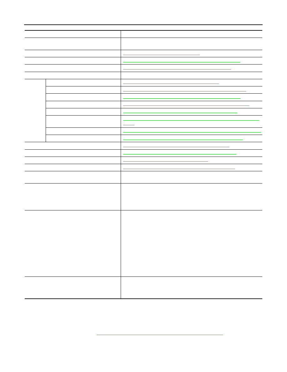
COMPONENT PARTS
*: These components are included in control valve assembly.
CVT CONTROL SYSTEM : TCM
INFOID:0000000009268059
• The vehicle driving status is judged based on the signals from the sensors, switches, and other control units,
and the optimal transaxle control is performed.
• For TCM control items, refer to
TM-274, "CVT CONTROL SYSTEM : System Description"
CVT CONTROL SYSTEM : ROM Assembly
INFOID:0000000009268060
• The ROM assembly is installed to control valve.
Component
Function
IPDM E/R
The TCM receives the A/C compressor feedback signal via CAN communica-
tions from the IPDM E/R.
TCM
TM-262, "CVT CONTROL SYSTEM : TCM"
Transmission range switch
TM-263, "CVT CONTROL SYSTEM : Transmission Range Switch"
Primary speed sensor
TM-263, "CVT CONTROL SYSTEM : Primary Speed Sensor"
CVT unit
—
Control
valve
ROM assembly*
TM-262, "CVT CONTROL SYSTEM : ROM Assembly"
CVT fluid temperature sensor*
TM-264, "CVT CONTROL SYSTEM : CVT Fluid Temperature Sensor"
Secondary pressure sensor*
TM-264, "CVT CONTROL SYSTEM : Secondary Pressure Sensor"
Primary pressure solenoid valve*
TM-265, "CVT CONTROL SYSTEM : Primary Pressure Solenoid Valve"
Low brake solenoid valve*
TM-265, "CVT CONTROL SYSTEM : Low Brake Solenoid Valve"
High clutch & reverse brake solenoid
valve*
TM-265, "CVT CONTROL SYSTEM : High Clutch & Reverse Brake Solenoid
Valve"
Torque converter clutch solenoid valve*
TM-265, "CVT CONTROL SYSTEM : Torque Converter Clutch Solenoid Valve"
Line pressure solenoid valve*
TM-266, "CVT CONTROL SYSTEM : Line Pressure Solenoid Valve"
Output speed sensor
TM-264, "CVT CONTROL SYSTEM : Output Speed Sensor"
Secondary speed sensor
TM-263, "CVT CONTROL SYSTEM : Secondary Speed Sensor"
G sensor
TM-266, "CVT CONTROL SYSTEM : G Sensor"
Overdrive control switch
TM-266, "CVT CONTROL SYSTEM : Overdrive Control Switch"
Combination meter
The TCM receives the sport mode switch signal via CAN communications from
the combination meter.
ABS actuator and electric unit (control unit)
The TCM receives the following signals via CAN communications from the ABS
actuator and electric unit (control unit).
• Vehicle speed signal
• VDC operation signal
• VDC malfunction signal
ECM
• For purposes including improving the feeling when shifting and preventing
drops in engine speed, control signals are exchanged between the ECM and
TCM, and real-time cooperative control is performed according to the vehicle
driving conditions. (Engine and CVT integrated control)
- Engine and CVT integrated control signal
• The TCM receives the following signals via CAN communications from the
ECM.
- Engine speed signal
- Accelerator pedal position signal
- Closed throttle position signal
• TCM sends and receives the following signals with ECM through CAN com-
munication to perform D position N idle control.
- N idle instruction signal
BCM
The TCM receives the following signals via CAN communications from the
BCM.
• Stop lamp switch signal
• Turn indicator signal