Nissan Versa Sedan. Instruction - part 838


  Index      Nissan     Nissan Versa Sedan (2014 year) - Service and Repair Instruction


Search            copyright infringement  


Content   ..  836  837  838  839   ..


Nissan Versa Sedan. Instruction - part 838


TM-258

< PRECAUTION >

[CVT: RE0F11A]

PRECAUTIONS

CAUTION:

• Be sure to turn the ignition switch OFF and disconnect the battery cable from the negative terminal

before any repair or inspection work. The open/short circuit of related switches, sensors, solenoid

valves, etc. will cause the MIL to light up.

• Be sure to connect and lock the connectors securely after work. A loose (unlocked) connector will

cause the MIL to light up due to an open circuit. (Be sure the connector is free from water, grease,

dirt, bent terminals, etc.)

• Be sure to route and secure the harnesses properly after work. Interference of the harness with a

bracket, etc. may cause the MIL to light up due to a short circuit.

• Be sure to connect rubber tubes properly after work. A misconnected or disconnected rubber tube

may cause the MIL to light up due to a malfunction of the EGR system or fuel injection system, etc.

• Be sure to erase the unnecessary malfunction information (repairs completed) from the TCM and

ECM before returning the vehicle to the customer.

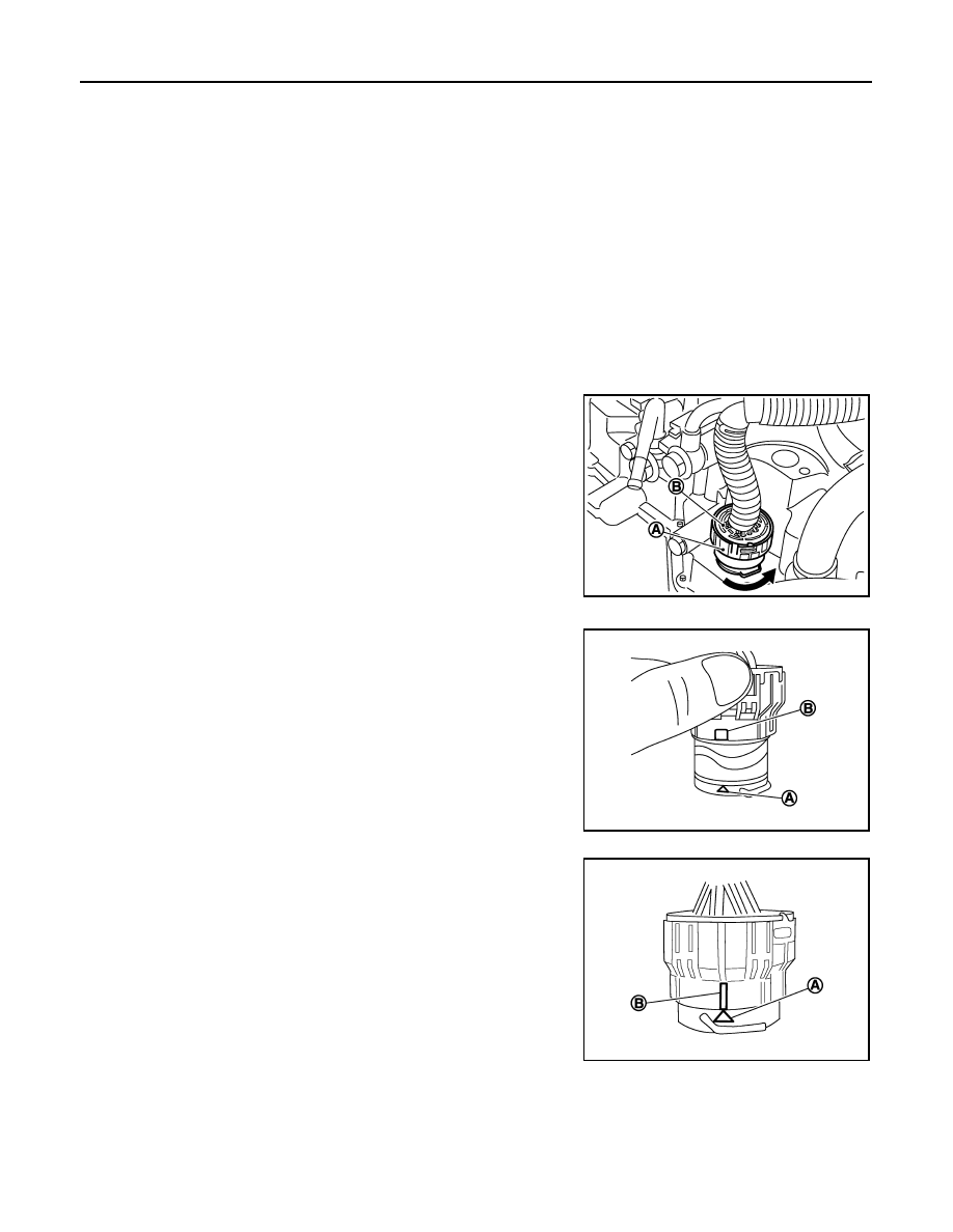
Removal and Installation Procedure for CVT Unit Connector

INFOID:0000000009268055

REMOVAL

• Rotate bayonet ring (A) counterclockwise. Pull out CVT unit har-

ness connector (B) upward and remove it.

INSTALLATION

1. Align marking (A) on CVT unit harness connector terminal with

marking (B) on bayonet ring. Insert CVT unit harness connector.

2. Rotate bayonet ring clockwise.

3. Rotate bayonet ring clockwise until marking (A) on CVT unit har-

ness connector terminal body is aligned with the slit (B) on bayo-

net ring as shown in the figure (correctly fitting condition).

CAUTION:

JSDIA1162ZZ

JPDIA0294ZZ

JPDIA0295ZZ

PRECAUTIONS

TM-259

< PRECAUTION >

[CVT: RE0F11A]

C

E

F

G

H

I

J

K

L

M

A

B

TM

N

O

P

• Securely align marking (A) on CVT unit harness connec-

tor terminal body with bayonet ring slit (B). Then, be care-

ful not to make a half fit condition as shown in the figure.

• Do not mistake the slit of bayonet ring for other dent por-

tion.

JPDIA0296ZZ

TM-260

< PREPARATION >

[CVT: RE0F11A]

PREPARATION

PREPARATION

PREPARATION

Special Service Tools

INFOID:0000000009268056

*: The O-ring as an unit part is set as a SST.

Commercial Service Tools

INFOID:0000000009268057

Tool number
Tool name

Description

1.

KV311039S0
Charging pipe set

2.

KV31103920*
O-ring

CVT fluid changing and adjustment

KV38107900
Protector
a: 

φ 32 mm

Installing drive shaft

JSDIA1844ZZ

PDIA1183J

Tool number
Tool name

Description

31197EU50A
Drive plate location guide
a: 

φ 25 mm

Installing transaxle assembly

Drift
a: 

φ 56 mm

b: 

φ 50 mm

Installing differential side oil seal

JPDIA0676ZZ

NT115

COMPONENT PARTS

TM-261

< SYSTEM DESCRIPTION >

[CVT: RE0F11A]

C

E

F

G

H

I

J

K

L

M

A

B

TM

N

O

P

SYSTEM DESCRIPTION

COMPONENT PARTS

CVT CONTROL SYSTEM
CVT CONTROL SYSTEM : Component Parts Location

INFOID:0000000009268058

COMPONENT DESCRIPTION

ALDIA0266ZZ

1.

IPDM E/R

2.

TCM

3.

Transmission range switch

4.

Primary speed sensor

5.

CVT unit

6.

Output speed sensor

7.

Secondary speed sensor

8.

G sensor

9.

Stop lamp switch

10. CVT shift selector

11. Overdrive control switch

12. Combination meter (type A)

13. Combination meter (type B)


Content   ..  836  837  838  839   ..