Nissan Versa Sedan. Instruction - part 832


  Index      Nissan     Nissan Versa Sedan (2014 year) - Service and Repair Instruction


Search            copyright infringement  


Content   ..  830  831  832  833   ..


Nissan Versa Sedan. Instruction - part 832


TM-234

< REMOVAL AND INSTALLATION >

[4AT: RE4F03C]

A/T SHIFT SELECTOR

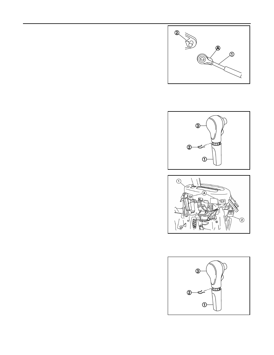
• When connecting the control cable (1) to the shift selector assem-

bly (2), face the grooved surface of the rib (A) up and insert the

control cable until it stops.

Disassembly and Assembly

INFOID:0000000009268017

DISASSEMBLY

1. Slide the shift selector handle cover (1) down.

CAUTION:

Do not damage the shift selector handle cover.

2. Pull out the lock pin (2).
3. Pull the shift selector handle (3) and shift selector handle cover

upward to remove them.

4. Remove the position lamp.

5. Disengage the hooks (A) (4 locations), and lift up the position

indication panel (1) to separate it from the shift selector assem-

bly (2).

CAUTION:

Do not damage the shift selector assembly.

ASSEMBLY

Assembly is in the reverse order of disassembly.

• Follow the procedure below to install the shift selector handle.

1. Install the lock pin (2) onto the shift selector handle (3).

2. Install the shift selector handle cover (1) onto the shift selector

handle.

3. Press the shift selector handle onto the shift selector until it

clicks.

CAUTION:

• When pressing the shift selector handle onto the shift

selector, do not press the shift selector handle button.

• Do not strike the shift selector handle to install it into

place.

4. After installing shift selector handle, pull the handle to check that

it does not become disconnected.

JSDIA1624ZZ

JSDIA1796ZZ

ALDIA0264ZZ

JSDIA1796ZZ

A/T SHIFT SELECTOR

TM-235

< REMOVAL AND INSTALLATION >

[4AT: RE4F03C]

C

E

F

G

H

I

J

K

L

M

A

B

TM

N

O

P

Inspection and Adjustment

INFOID:0000000009268018

INSPECTION

1. Move the shift selector to “P” position, and turn ignition switch ON.
2. Check that shift selector can be moved to other than “P” position when brake pedal is depressed. Also

check that shift selector can be moved from “P” position only when brake pedal is depressed.

3. Move the shift selector and check for excessive effort, sticking, noise or rattle.
4. Check that shift selector stops at each position with the feel of engagement when it is moved through all

the positions. Check that the actual position of shift selector matches the position shown by shift position

indicator and instruction lever on the transaxle.

5. The method of operating shift selector to individual positions cor-

rectly should be as shown.

6. When shift selector handle button is pressed in “P”, “R”, “N”, “D”,

“2” or “1” position without applying forward/backward force to

shift selector, check button operation for sticking.

7. Check that back-up lamps illuminate only when shift selector is

placed in the “R” position.

8. Check that back-up lamps do not illuminate when shift selector

is pushed toward the “R” position when in the “P” or “N” position.

CAUTION:

Check the lighting without pressing shift selector handle

button.

9. Check that the engine can only be started with shift selector in the “P” and “N” positions.
10. Check that transaxle is locked completely when shift selector is in “P” position.

ADJUSTMENT

1. Move shift selector to “ P” position.

CAUTION:

Rotate the wheels at least a quarter turn and be certain the transaxle is locked in the "P" position.

2. Loosen the control cable nut (A).
3. Place instruction lever (B) to “P” position.

CAUTION:

Do not apply force to the instruction lever.

4. Tighten the control cable nut. Refer to 

TM-236, "Exploded View"

.

CAUTION:

Do not move the instruction lever when tightening.

SCIA6984E

JSDIA1951ZZ

TM-236

< REMOVAL AND INSTALLATION >

[4AT: RE4F03C]

CONTROL CABLE

CONTROL CABLE

Exploded View

INFOID:0000000009268019

Removal and Installation

INFOID:0000000009268020

CAUTION:

Always apply the parking brake before performing removal and installation.

REMOVAL

1. Remove the battery. Refer to 

PG-63, "Removal and Installation"

.

2. Remove the TCM and bracket. Refer to 

TM-241, "Removal and Installation"

.

3. Remove the IPDM E/R. Refer to 

PCS-56, "Removal and Installation"

.

4. Remove the center console. Refer to 

IP-23, "Removal and Installation"

.

5. Remove the control cable from the shift selector assembly.
6. Disengage the pawls (B) of the grommet (A), and pull down-

wards to remove.

7. Remove the control cable nut from the instruction lever.

1.

Bracket B

2.

Lock plate

3.

Transaxle assembly

4.

Bracket A

5.

Control cable

6.

Shift selector assembly

A: Instruction lever

B: Grommet

JSDIA1921GB

JSDIA1809ZZ

CONTROL CABLE

TM-237

< REMOVAL AND INSTALLATION >

[4AT: RE4F03C]

C

E

F

G

H

I

J

K

L

M

A

B

TM

N

O

P

8. Remove the lock plate (1).

9. Lift up the heat plate.
10. Remove the control cable (1) from the bracket (2).

11. Remove the control cable from the vehicle.
12. Remove bracket.

INSTALLATION

Installation is in the reverse order of removal.

• From below the vehicle, press the grommet (A) into place until the

pawls (B) make a click sound.

CAUTION:

Check that pulling down on the grommet does not disconnect

it.

• Pay attention to the following when connecting the control cable to the shift selector.

1. When connecting the control cable (1) to the shift selector

assembly (2), face the grooved surface of the rib (A) up and

insert the control cable until it stops.

JSDIA1812ZZ

: Front

JPDIA0107ZZ

JSDIA1809ZZ

JSDIA1624ZZ


Content   ..  830  831  832  833   ..