Nissan Versa Sedan. Instruction - part 831


  Index      Nissan     Nissan Versa Sedan (2014 year) - Service and Repair Instruction


Search            copyright infringement  


Content   ..  829  830  831  832   ..


Nissan Versa Sedan. Instruction - part 831


TM-230

< PERIODIC MAINTENANCE >

[4AT: RE4F03C]

A/T FLUID

PERIODIC MAINTENANCE

A/T FLUID

Inspection

INFOID:0000000009268014
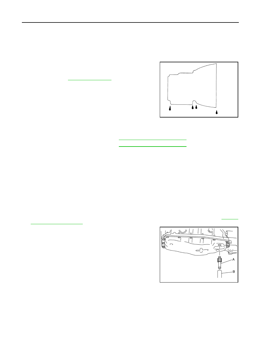
FLUID LEAKAGE

• Check transaxle surrounding area (oil seal and plug etc.)for fluid

leakage.

• If anything is found, repair or replace damaged parts and adjust A/

fluid level. Refer to 

TM-231, "Adjustment"

.

Changing

INFOID:0000000009267877

CAUTION:

• Use only Genuine NISSAN Matic S ATF. Do not mix with other ATF.

• Using ATF other than Genuine NISSAN Matic S ATF will cause deterioration driveability and A/T

durability, and may damagethe A/T, which is not covered by the warranty.

• Always use shop paper. Never use shop cloth.

• Replace a drain plug gasket with new ones at the final stage of the operation when installing.

• Use caution when looking into the drain hole as there is a risk of dripping fluid entering the eye.

• After replacement, always perform an ATF leakage check.
1. Select “Data Monitor” in “TRANSMISSION” using CONSULT.
2. Select “FLUID TEMP”, and check that the A/T fluid temperature is 40 

°C (104°F) or less.

3. Check that the selector lever is in the “P” position, then completely engage the parking brake.
4. Lift up the vehicle.
5. Remove the drain plug and overflow tube, and then drain the ATF from the oil pan. Refer to 

TM-242,

"Removal and Installation"

.

6. Install the charging pipe set (KV311039S0) (A) into the drain

hole.

CAUTION:

Tighten the charging pipe by hand.

7. Install the ATF changer hose (B) to the charging pipe.

CAUTION:

Press the ATF changer hose all the way onto the charging

pipe until it stops.

8. Fill approximately 3 liters (2-5/8 lmp qt) of the ATF.
9. Remove the ATF changer hose and charging pipe, then install

the drain plug.

NOTE:

Perform this work quickly because ATF leaks.

10. Lift down the vehicle.
11. Start the engine.
12. While depressing the brake pedal, shift the selector lever to the entire position from “P” to “1”, and shift it

to the “P” position.

NOTE:

SMA146B

A/T fluid

: Refer to 

TM-254, "General Specification"

.

Fluid capacity

: Refer to 

TM-254, "General Specification"

.

JSDIA1950ZZ

A/T FLUID

TM-231

< PERIODIC MAINTENANCE >

[4AT: RE4F03C]

C

E

F

G

H

I

J

K

L

M

A

B

TM

N

O

P

Hold the lever at each position for 5 seconds.

13. Check that the CONSULT “Data Monitor” in “FLUID TEMP ” is 35 to 45

°C (95 to 113°F).

14. Stop the engine.
15. Lift up the vehicle.
16. Remove the drain plug, and then drain the ATF from the oil pan.
17. Repeat steps 6 to 16 (one time).
18. Install the overflow tube. Refer to 

TM-242, "Removal and Installation"

.

CAUTION:

Be sure to tighten to the specified torque. If it is not tightened to the specified torque, the tube may

be damaged.

19. Install the charging pipe set (KV311039S0) (A) into the drain

hole.

CAUTION:

Tighten the charging pipe by hand.

20. Install the ATF changer hose (B) to the charging pipe.

CAUTION:

Press the ATF changer hose all the way onto the charging

pipe until it stops.

21. Fill approximately 3 liters (2-5/8 lmp qt) of the ATF.
22. Remove the ATF changer hose and charging pipe, then install

the drain plug.

NOTE:

Perform this work quickly because ATF leaks.

23. Lift down the vehicle.
24. Start the engine.
25. While depressing the brake pedal, shift the selector lever to the entire position from “P” to “1”, and shift it

to the “P” position.

NOTE:

Hold the lever at each position for 5 seconds.

26. Check that the CONSULT “Data Monitor” in “FLUID TEMP ” is 35 to 45

°C (95 to 113°F).

27. Lift up the vehicle.
28. Remove the drain plug and check that ATF is drained out from the overflow tube.

CAUTION:

Perform this work with the vehicle idling.

NOTE:

If the ATF is not drained out, refer to "Adjustment" and add ATF.

29. When the flow of ATF slows to a drip, tighten the drain plug to the specified torque. Refer to 

TM-242,

"Removal and Installation"

.

CAUTION:

Do not reuse drain plug gasket.

30. Lift down the vehicle.
31. Stop the engine.

Adjustment

INFOID:0000000009267878

CAUTION:

• Use only Genuine NISSAN Matic S ATF. Never mix with other ATF.

• Using ATF other than Genuine NISSAN Matic S ATF will cause deterioration driveability and A/T

durability, and may damagethe A/T, which is not covered by the warranty.

• During adjusting of the ATF level, check CONSULT so that the fluid temperature may be maintained

from 35 to 45

°C (95 to 113°F).

• Use caution when looking into the drain hole as there is a risk of dripping fluid entering the eye.

JSDIA1950ZZ

A/T fluid

: Refer to 

TM-254, "General Specification"

.

Fluid capacity

: Refer to 

TM-254, "General Specification"

.

TM-232

< PERIODIC MAINTENANCE >

[4AT: RE4F03C]

A/T FLUID

1. Check that the selector lever is in the “P” position, then completely engage the parking brake.
2. Start the engine.
3. Adjust the ATF to be approximately 40

°C (104°F).

NOTE:

The ATF is largely affected by temperature. Therefore be sure to use CONSULT and check the “FLUID

TEMP” under “TRANSMISSION” in “Data Monitor” while adjusting.

4. While depressing the brake pedal, shift the selector lever to the entire position from “P” to “1”, and shift it

to the “P” position.

NOTE:

Hold the lever at each position for 5 seconds.

5. Lift up the vehicle.
6. Check that there is no ATF leakage.
7. Remove the drain plug. Refer to 

TM-242, "Removal and Installation"

.

8. Install the charging pipe set (KV311039S0) (A) into the drain

plug hole.

CAUTION:

Tighten the charging pipe by hand.

9. Install the ATF changer hose (B) to the charging pipe.

CAUTION:

Press the ATF changer hose all the way onto the charging

pipe until it stops.

10. Fill approximately 0.5 liters (1/2 lmp qt) of the ATF.
11. Remove the ATF changer hose from the charging pipe, and

check that the ATF drains out from the charging pipe. If it does

not drain out, perform charging again.

CAUTION:

Perform this work with the vehicle idling.

12. When the flow of ATF slows to a drip, disconnect the charging pipe from the oil pan.
13. Tighten the drain plug to the specified torque. Refer to 

TM-242, "Removal and Installation"

.

CAUTION:

Never reuse drain plug gasket.

14. Lift down the vehicle.
15. Stop the engine.

JSDIA1950ZZ

A/T SHIFT SELECTOR

TM-233

< REMOVAL AND INSTALLATION >

[4AT: RE4F03C]

C

E

F

G

H

I

J

K

L

M

A

B

TM

N

O

P

REMOVAL AND INSTALLATION

A/T SHIFT SELECTOR

Exploded View

INFOID:0000000009268015

Removal and Installation

INFOID:0000000009268016

CAUTION:

Always apply the parking brake before performing removal and installation.

REMOVAL

1. Move the shift selector to the “N” position.
2. Remove the shift selector handle. Refer to 

TM-234, "Disassembly and Assembly"

.

3. Remove the center console. Refer to 

IP-23, "Removal and Installation"

.

4. Disconnect the harness connector from the shift selector.
5. Move the shift selector to the “P” position. 
6. Remove the key interlock cable from the shift selector assembly. Refer to 

TM-239, "Removal and Installa-

tion"

.

7. Remove the control cable from the shift selector assembly. Refer to 

TM-236, "Removal and Installation"

.

8. Remove the shift selector assembly. 

INSTALLATION

Installation is in the reverse order of removal.

1.

Shift selector handle

2.

Lock pin

3.

Shift selector handle cover

4.

Position indication panel

5.

Shift selector assembly

ALDIA0263GB


Content   ..  829  830  831  832   ..