Nissan Versa Sedan. Instruction - part 805


  Index      Nissan     Nissan Versa Sedan (2014 year) - Service and Repair Instruction


Search            copyright infringement  


Content   ..  803  804  805  806   ..


Nissan Versa Sedan. Instruction - part 805


TM-126

< BASIC INSPECTION >

[4AT: RE4F03C]

A/T FLUID COOLER

A/T FLUID COOLER

Cleaning

INFOID:0000000009315569

Whenever the A/T is repaired, overhauled, or replaced, the A/T fluid cooler mounted in the radiator must be

inspected and cleaned.

Metal debris and friction material, if present, can become trapped in the A/T fluid cooler. This debris can con-

taminate the newly serviced A/T or, in severe cases, can block or restrict the flow of A/T fluid. In either case,

malfunction of the newly serviced A/T may result.

Debris, if present, may build up as A/T fluid enters the cooler inlet. It will be necessary to back flush the cooler

through the cooler outlet in order to flush out any built up debris.

A/T FLUID COOLER CLEANING PROCEDURE

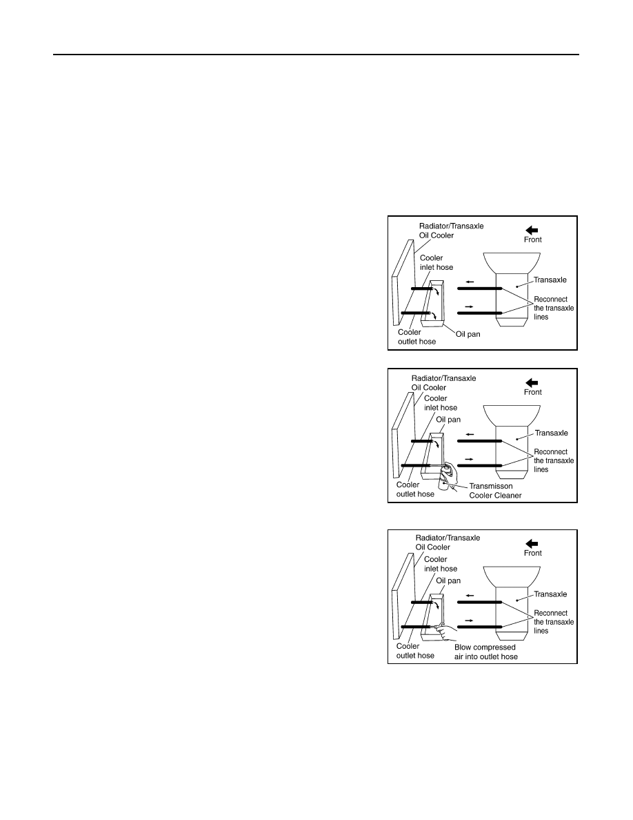
1. Identify the A/T inlet and outlet fluid cooler hoses.
2. Position an oil pan under the A/T inlet and outlet fluid cooler

hoses.

3. Disconnect the A/T fluid cooler inlet and outlet rubber hoses

from the steel cooler tubes or bypass valve.

NOTE:

Replace the cooler hoses if rubber material from the hose

remains on the tube fitting.

4. Allow any A/T fluid that remains in the cooler hoses to drain into

the oil pan.

5. Insert the extension adapter hose of a can of Transmission

Cooler Cleaner (Nissan P/N 999MP-AM006) into the cooler out-

let hose.

CAUTION:

• Wear safety glasses and rubber gloves when spraying the

Transmission Cooler Cleaner.

• Spray Transmission Cooler Cleaner only with adequate

ventilation.

• Avoid contact with eyes and skin.

• Do not breathe vapors or spray mist.

6. Hold the hose and can as high as possible and spray Transmis-

sion Cooler Cleaner in a continuous stream into the cooler outlet

hose until A/T fluid flows out of the cooler inlet hose for 5 seconds. 

7. Insert the tip of an air gun into the end of the cooler outlet hose.
8. Wrap a shop rag around the air gun tip and end of cooler outlet

hose.

9. Blow compressed air regulated to 5 - 9 kg/cm

2

 (490 - 883 kPa, 71 - 128 psi) through the cooler outlet hose

for 10 seconds to force out any remaining A/T fluid.

10. Repeat steps 5 through 9 three additional times.
11. Position an oil pan under the banjo bolts that connect the A/T fluid cooler steel lines to the A/T.
12. Remove the banjo bolts.
13. Flush each steel line from the cooler side back toward the A/T by spraying Transmission Cooler Cleaner

in a continuous stream for 5 seconds. 

SCIA5628E

SCIA5629E

SCIA5630E

A/T FLUID COOLER

TM-127

< BASIC INSPECTION >

[4AT: RE4F03C]

C

E

F

G

H

I

J

K

L

M

A

B

TM

N

O

P

14. Blow compressed air regulated to 5 - 9 kg/cm

2

 (490 - 883 kPa, 71 - 128 psi) through each steel line from

the cooler side back toward the A/T for 10 seconds to force out any remaining A/T fluid.

15. Ensure all debris is removed from the steel cooler lines.
16. Ensure all debris is removed from the banjo bolts and fittings.
17. Perform "A/T FLUID COOLER DIAGNOSIS PROCEDURE".

A/T FLUID COOLER DIAGNOSIS PROCEDURE

NOTE:

Insufficient cleaning of the cooler inlet hose exterior may lead to inaccurate debris identification.
1. Position an oil pan under the A/T inlet and outlet cooler hoses.
2. Clean the exterior and tip of the cooler inlet hose.
3. Insert the extension adapter hose of a can of Transmission

Cooler Cleaner (Nissan P/N 999MP-AM006) into the cooler out-

let hose.

CAUTION:

• Wear safety glasses and rubber gloves when spraying the

Transmission Cooler Cleaner.

• Spray Transmission Cooler Cleaner only with adequate

ventilation.

• Avoid contact with eyes and skin.

• Do not breathe vapors or spray mist.

4. Hold the hose and can as high as possible and spray Transmis-

sion Cooler Cleaner in a continuous stream into the cooler outlet

hose until A/T fluid flows out of the cooler inlet hose for 5 seconds.

5. Tie a common white, basket-type coffee filter to the end of the

cooler inlet hose.

6. Insert the tip of an air gun into the end of the cooler outlet hose.
7. Wrap a shop rag around the air gun tip and end of cooler outlet

hose.

8. Blow compressed air regulated to 5 - 9 kg/cm

2

 (490 - 883 kPa,

71 - 128 psi) through the cooler outlet hose to force any remain-

ing A/T fluid into the coffee filter.

9. Remove the coffee filter from the end of the cooler inlet hose.
10. Perform "A/T FLUID COOLER INSPECTION PROCEDURE".

A/T FLUID COOLER INSPECTION PROCEDURE

SCIA5629E

SCIA5631E

SCIA5632E

TM-128

< BASIC INSPECTION >

[4AT: RE4F03C]

A/T FLUID COOLER

1. Inspect the coffee filter for debris.
a. If small metal debris less than 1mm (0.040 in) in size or metal

powder is found in the coffee filter, this is normal. If normal

debris is found, the A/T fluid cooler/radiator can be re-used and

the procedure is ended.

b. If one or more pieces of debris are found that are over 1mm

(0.040 in) in size and/or peeled clutch facing material is found in

the coffee filter, the A/T fluid cooler is not serviceable. The A/T

fluid cooler/radiator must be replaced and the inspection proce-

dure is ended. Refer to 

CO-14, "Exploded View"

.

A/T FLUID COOLER FINAL INSPECTION

After performing all procedures, ensure that all remaining oil is cleaned from all components.

SCIA2967E

SCIA5659E

STALL TEST

TM-129

< BASIC INSPECTION >

[4AT: RE4F03C]

C

E

F

G

H

I

J

K

L

M

A

B

TM

N

O

P

STALL TEST

Work Procedure

INFOID:0000000009267879

INSPECTION

1. Inspect the amount of engine oil. Replenish the engine oil if necessary. Refer to 

LU-8, "Inspection"

.

2. Drive for about 10 minutes to warm up the vehicle so that the A/T fluid temperature is 50 to 80

°C (122 to

176

°F).

3. Inspect the amount of ATF. Replenish if necessary. Refer to 

TM-230, "Inspection"

.

4. Securely engage the parking brake so that the tires do not turn.
5. Start the engine, apply foot brake, and place selector lever in “D” position.
6. Gradually press down the accelerator pedal while holding down the foot brake.
7. Quickly read off the stall speed, then quickly release the accelerator pedal.

CAUTION:

Never hold down the accelerator pedal for more than 5 seconds during this test.

8. Shift the selector lever to “N” position.
9. Cool down the ATF.

CAUTION:

Run the engine at idle for at least 1 minute.

10. Repeat steps 6 through 9 with selector lever in “1”,  “2” and “R” positions.

JUDGMENT OF STALL TEST

O: Stall speed within standard value position
H: Stall speed higher than standard value
L: Stall speed lower than standard value

Stall speed

: Refer to 

TM-254, "Stall Speed"

.

Selector lever position

Possible location of malfunction

“D” “2” “1” “R”

Stall speed

H

H

H

O

• Low  clutch
• one-way clutch

O

O

H

H

Low and reverse brake

O

O

O

H

Reverse clutch

L

L

L

L

• Engine
• Torque converter one-way clutch

H

H

H

H

Line pressure low


Content   ..  803  804  805  806   ..