Nissan Versa Sedan. Instruction - part 788
TM-58
< SERVICE DATA AND SPECIFICATIONS (SDS)
[5MT: RS5F91R]
SERVICE DATA AND SPECIFICATIONS (SDS)
SERVICE DATA AND SPECIFICATIONS (SDS)
SERVICE DATA AND SPECIFICATIONS (SDS)
General Specifications
INFOID:0000000009267812
Transaxle type
RS5F91R
Engine type
HR16DE
Model code number
3AM0C
Number of speed
5
Synchromesh type
Warner
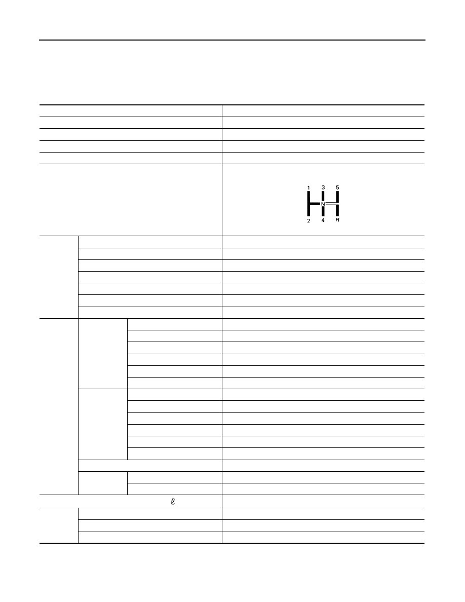
Shift pattern
Gear ratio
1st
3.7273
2nd
2.0476
3rd
1.3929
4th
1.0294
5th
0.8205
Reverse
3.5455
Final gear
4.0667
Number of
teeth
Input gear
1st
11
2nd
21
3rd
28
4th
34
5th
39
Reverse
11
Main gear
1st
41
2nd
43
3rd
39
4th
35
5th
32
Reverse
39
Reverse idler gear
26
Final gear
Final gear/Pinion
61/15
Side gear/Pinion mate gear
13/9
Oil capacity (Reference)
(US pt, Imp pt)
Approx. 2.67 (5-5/8, 4-3/4)
Remarks
Reverse brake
Installed
Double-cone synchronizer
1st and 2nd
Speedometer drive gear
Not installed
SCIA0821E