Nissan Versa Sedan. Instruction - part 722


  Index      Nissan     Nissan Versa Sedan (2014 year) - Service and Repair Instruction


Search            copyright infringement  


Content   ..  720  721  722  723   ..


Nissan Versa Sedan. Instruction - part 722


DRIVER AIR BAG MODULE

SR-13

< REMOVAL AND INSTALLATION >

C

D

E

F

G

I

J

K

L

M

A

B

SR

N

O

P

• Do not strike or impact the driver air bag module.

• Replace the driver air bag module if it has been dropped

or sustained an impact.

• Do not insert any foreign objects (screwdriver, etc.) into the driver air bag module.

• Do not disassemble the driver air bag module.

• Do not expose the driver air bag module to temperatures exceeding 90 

°C (194 °F).

• Do not allow oil, grease, detergent, or water to come in contact with the driver air bag module.
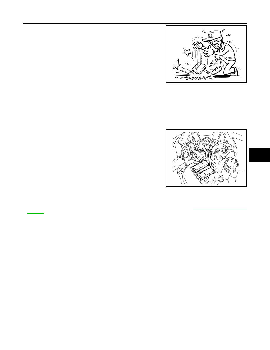
INSTALLATION

Installation is in the reverse order of removal.

CAUTION:

• Connect the driver air bag module harnesses (A) and route

through the hook (B) as shown.

• Do not damage the harness while installing.

• If malfunction is detected by the air bag warning lamp, after repair or replacement of the malfunc-

tioning parts, reset the memory using self-diagnosis or CONSULT. Refer to 

SRC-13, "SRS Operation

Check"

.

• After the work is completed, check that no system malfunction is detected by air bag warning lamp.

JMHIA0009ZZ

ALHIA0343ZZ

SR-14

< REMOVAL AND INSTALLATION >

SPIRAL CABLE

SPIRAL CABLE

Exploded View

INFOID:0000000009266923

Removal and Installation

INFOID:0000000009266924

WARNING:

Always observe the following items for preventing accidental activation.

• Before servicing, turn ignition switch OFF, disconnect both battery terminals, then wait at least three

minutes or more.

• Always work from the side of air bag module. Do not work in front of it.

• Do not use the air tools or electric tools for servicing.

• Always place air bag module with pad side facing upward.

• Do not cause impact to the air bag module by dropping etc. Replace the air bag module if it has been

dropped or sustained an impact.

REMOVAL

1. Remove the steering wheel. Refer to 

ST-8, "Removal and Installation"

.

2. Remove the steering column covers. Refer to 

IP-15, "Removal and Installation"

.

1.

Steering column upper cover

2.

Combination switch

3.

Spiral cable

4.

Steering wheel

5.

Driver air bag module

6.

Steering lock escutcheon

7.

Steering column lower cover

8.

Steering column assembly

Pawl

ALHIA0195GB

SPIRAL CABLE

SR-15

< REMOVAL AND INSTALLATION >

C

D

E

F

G

I

J

K

L

M

A

B

SR

N

O

P

3. Disconnect the harness connectors (A) and (B) from the spiral

cable body side.

4. Remove the spiral cable screws.
5. Release the pawls using a suitable tool (A), then remove the spiral cable.

CAUTION:

• Do not impact the spiral cable.

• Replace the spiral cable if it has been dropped or sustained

an impact.

• Do not disassemble the spiral cable.

• Do not apply lubricant to the spiral cable.

• Do not allow oil, grease, detergent, or water to come in contact with the spiral cable.

INSTALLATION

Installation is in the reverse order of removal.

CAUTION:

ALHIA0196ZZ

Pawl

ALHIA0197ZZ

JMHIA0009ZZ

SR-16

< REMOVAL AND INSTALLATION >

SPIRAL CABLE

• The spiral cable may snap during steering operation if the

cable is installed in an improper position.

The neutral position is set as follows.

• Carefully turn the spiral cable clockwise to the end position.

Then turn it counterclockwise (about two and a half turns) and

stop turning at the mark (B) where the stopper insertion holes

are in the same position.

• The service part is installed in the neutral position by the

stopper and can be set without adjusting after the stopper is

removed.

• Do not over turn the spiral cable or go beyond the number of

turns required. (This will cause the cable to snap)

• Carefully align the spiral cable locating pin (A) to the steering

wheel locating pin hole (C).

• If malfunction is detected by the air bag warning lamp, after repair or replacement of the malfunc-

tioning parts, reset the memory using self-diagnosis or CONSULT. Refer to 

SRC-13, "SRS Operation

Check"

.

• After the work is completed, check that no system malfunction is detected by air bag warning lamp.

ALHIA0198ZZ


Content   ..  720  721  722  723   ..