Nissan Versa Sedan. Instruction - part 622
PCS-74
< BASIC INSPECTION >
[POWER DISTRIBUTION SYSTEM]
DIAGNOSIS AND REPAIR WORK FLOW
BASIC INSPECTION
DIAGNOSIS AND REPAIR WORK FLOW
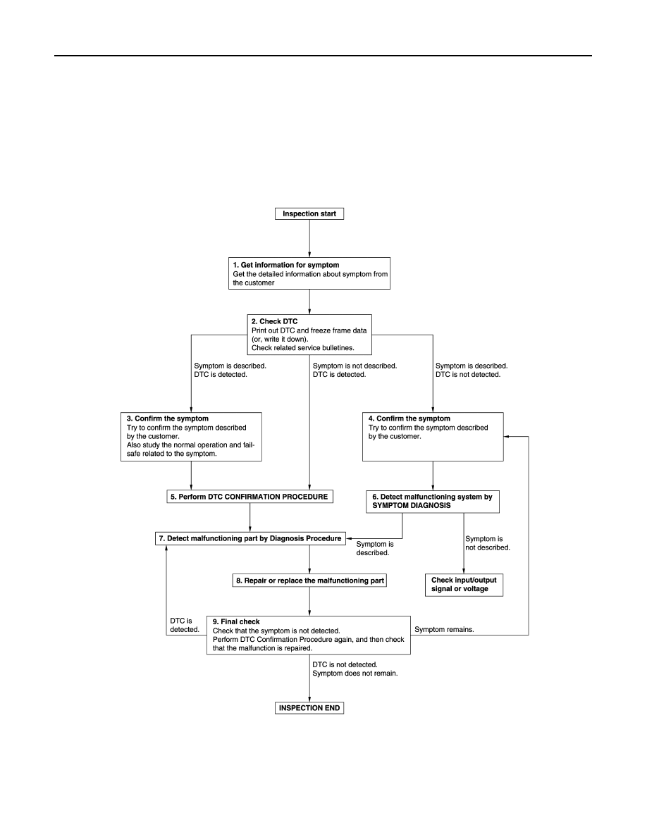
Work Flow
INFOID:0000000009266463
OVERALL SEQUENCE
DETAILED FLOW
JMKIA8652GB