Nissan Versa Sedan. Instruction - part 607
PCS-14
< ECU DIAGNOSIS INFORMATION >
[IPDM E/R (WITH I-KEY)]
IPDM E/R (INTELLIGENT POWER DISTRIBUTION MODULE ENGINE ROOM)
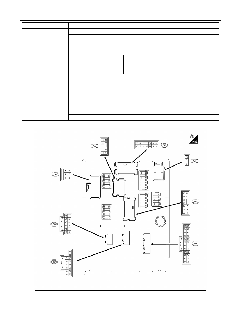
TERMINAL LAYOUT
PHYSICAL VALUES
ST/INHI RLY
Ignition switch ON
Off
At engine cranking
INHI ON
→ ST ON
The status of starter relay or starter control relay cannot be recognized by
the battery voltage malfunction, etc. when the starter relay is ON and the
starter control relay is OFF.
UNKWN
DETENT SW
Ignition switch ON
• Press the selector button with se-
lector lever in P position.
• Selector lever in any position oth-
er than P.
Off
Release the selector button with selector lever in P position.
On
DTRL REQ
Daytime running lamps OFF
Off
Daytime running lamps ON
On
THFT HRN REQ
Not operation
Off
• Panic alarm is activated
• Theft warning alarm is activated
On
HORN CHIRP
Not operated
Off
Door locking with keyfob (horn chirp mode)
On
Monitor Item
Condition
Value/Status
ALMIA0600ZZ