Nissan Versa Sedan. Instruction - part 605
PCS-6
< SYSTEM DESCRIPTION >
[IPDM E/R (WITH I-KEY)]
SYSTEM
SYSTEM
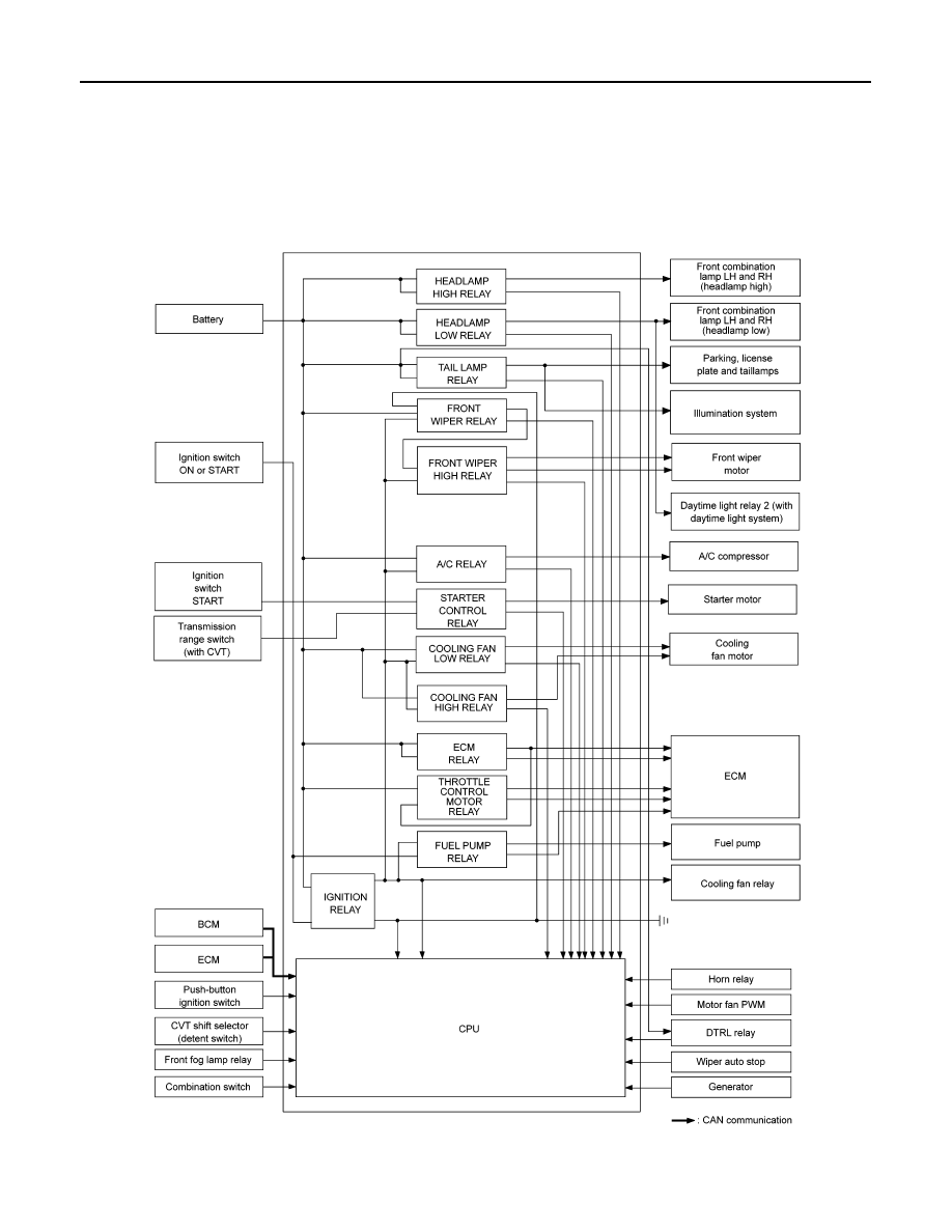
RELAY CONTROL SYSTEM
RELAY CONTROL SYSTEM : System Diagram
INFOID:0000000009266408
SYSTEM DIAGRAM
AWMIA1420GB
|
|
|
PCS-6 < SYSTEM DESCRIPTION > [IPDM E/R (WITH I-KEY)] SYSTEM SYSTEM RELAY CONTROL SYSTEM INFOID:0000000009266408 SYSTEM DIAGRAM AWMIA1420GB |