Nissan Versa Sedan. Instruction - part 591


  Index      Nissan     Nissan Versa Sedan (2014 year) - Service and Repair Instruction


Search            copyright infringement  


Content   ..  589  590  591  592   ..


Nissan Versa Sedan. Instruction - part 591


MWI

SYSTEM

MWI-63

< SYSTEM DESCRIPTION >

[TYPE B]

C

D

E

F

G

H

I

J

K

L

M

B

A

O

P

SPEEDOMETER
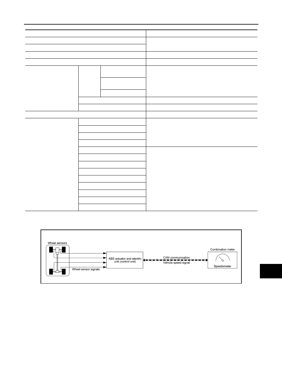
SPEEDOMETER : System Diagram

INFOID:0000000009266504

SPEEDOMETER : System Description

INFOID:0000000009266505

The ABS actuator and electric unit (control unit) receives each wheel speed sensor signal and provides a vehi-

cle speed signal to the combination meter via CAN communication.

TACHOMETER

Function

Specifications

Speedometer

Reset to zero by suspending communication.

Tachometer

Illumination control

When suspending communication, changes to nighttime mode.

Shift position indicator

When suspending communication, not indicate.

Information display

Trip com-
puter

Current fuel consump-
tion

• When reception time of an abnormal signal is 2 seconds or 

less, the last received datum is used for calculation to indi-
cate the result.

• When reception time of an abnormal signal is more than two 

seconds, the last result calculated during normal condition is 
indicated.

Average fuel consump-
tion

Distance to empty

Engine coolant temperature gauge

Reset to zero by suspending communication.

Odo/trip meter

An indicated value is maintained at communications blackout.

Buzzer

The buzzer turns OFF by suspending communication.

Warning lamp/indicator lamp

ABS warning lamp

The lamp turns ON by suspending communication.

Malfunction indicator lamp (MIL)

EPS warning lamp

Brake warning lamp

High beam indicator lamp

The lamp turns OFF by suspending communication.

Turn signal indicator lamp

Door warning lamp

Light indicator lamp

Oil pressure warning lamp

Key warning lamp

O/D OFF indicator lamp

Shift P warning lamp

Engine start operation indicator lamp

AWNIA2379GB

MWI-64

< SYSTEM DESCRIPTION >

[TYPE B]

SYSTEM

TACHOMETER : System Diagram

INFOID:0000000009266506

TACHOMETER : System Description

INFOID:0000000009266507

The crank position sensor sends a crankshaft position signal to the ECM. The ECM provides an engine speed

signal to the combination meter via CAN communication lines. The tachometer indicates engine speed in rev-

olutions per minute (rpm).

SHIFT POSITION INDICATOR
SHIFT POSITION INDICATOR : System Diagram

INFOID:0000000009266508

SHIFT POSITION INDICATOR : System Description

INFOID:0000000009266509

DESCRIPTION

The combination meter receives the shift position signal from TCM via CAN communication, and displays the

position of the shift indicator.

OIL PRESSURE WARNING LAMP
OIL PRESSURE WARNING LAMP : System Diagram

INFOID:0000000009266510

SYSTEM DIAGRAM

OIL PRESSURE WARNING LAMP : System Description

INFOID:0000000009266511

DESCRIPTION

The combination meter turns the oil pressure warning lamp ON when receiving a signal from the ECM via

CAN communication.

METER ILLUMINATION CONTROL

JSNIA2462GB

AWNIA1914GB

JSNIA4039GB

MWI

SYSTEM

MWI-65

< SYSTEM DESCRIPTION >

[TYPE B]

C

D

E

F

G

H

I

J

K

L

M

B

A

O

P

METER ILLUMINATION CONTROL : System Diagram

INFOID:0000000009266512

METER ILLUMINATION CONTROL : System Description

INFOID:0000000009266513

DESCRIPTION

Meter Illumination Control Function

• Meter illumination control is enabled when the meter receives a signal from the BCM that the combination

switch is in the 1st or 2nd position and the meter switches from Daytime mode to Nighttime mode.

Meter Illumination Control Switch

The operation of the illumination control switch changes brightness of the meter illumination.

INFORMATION DISPLAY
INFORMATION DISPLAY : System Diagram

INFOID:0000000009266514

INFORMATION DISPLAY : System Description

INFOID:0000000009266515

DESCRIPTION

• The combination meter receives signals from switches, sensors and modules for operating the following

functions on  the information display.

- Odo/trip meter

AWNIA2456GB

Condition

Meter illumination

Combination switch
(lighting switch)

1ST or 2ND position

Nighttime mode

Off

Daytime mode

Meter illumination

The number of adjustable 

steps

Daytime

12 step

Nighttime

12 step

AWNIA2439GB

MWI-66

< SYSTEM DESCRIPTION >

[TYPE B]

SYSTEM

- Engine coolant temperature gauge

- Fuel gauge

- Trip computer

- Interrupt indication

- Meter illumination level

- Setting

- Low fuel warning

- Loose fuel cap warning

ODO/TRIP METER

The combination meter calculates mileage using the vehicle speed signal from the ABS actuator and electric

unit (control unit) and displays the mileage on the information display.

ENGINE COOLANT TEMPERATURE GAUGE

The engine coolant temperature gauge indicates the engine coolant temperature.

The ECM provides an engine coolant temperature signal to the combination meter  via CAN communication. 

FUEL GAUGE

Control Outline

The fuel level sensor unit sends a variable resistor signal to the combination meter. The fuel gauge indicates

the approximate fuel level in the fuel tank. 

Refuel Control

The unit detects the driver is refueling the vehicle and accelerates the fuel gauge segment movement if the
fuel level changes by 9   (2-3/8 US, 2 lmp gal) or more.

Lighting segment-resistance relationship

INTERRUPT INDICATION

Low Fuel Warning

The low fuel warning turns ON when the fuel level in the fuel tank reaches approximately 7   (1-7/8 US gal, 1-

1/2 Imp gal).

JSNIA4205GB


Content   ..  589  590  591  592   ..