Nissan Versa Sedan. Instruction - part 587
MWI
FUEL LEVEL SENSOR SIGNAL CIRCUIT
MWI-47
< DTC/CIRCUIT DIAGNOSIS >
[TYPE A]
C
D
E
F
G
H
I
J
K
L
M
B
A
O
P
3.
CHECK FUEL LEVEL SENSOR GROUND CIRCUIT
1. Check continuity between combination meter harness connector M24 terminal 26 and fuel level sensor
unit and fuel pump harness connector B44 terminal 5.
2. Check continuity between fuel level sensor unit and fuel pump harness connector B44 terminal 5 and
ground.
Is the inspection result normal?
YES
>> GO TO 4
NO
>> Repair harness or connector.
4.
CHECK INSTALLATION CONDITION
Check fuel level sensor unit installation, and verify the float arm does not interfere or bind with the internal
components in the fuel tank.
Is the inspection result normal?
YES
>> Inspection End.
NO
>> Install the fuel level sensor unit properly.
Component Inspection
INFOID:0000000009266606
1.
REMOVE FUEL LEVEL SENSOR UNIT
Remove the fuel level sensor unit. Refer to
FL-5, "Removal and Installation"
.
>> GO TO 2.
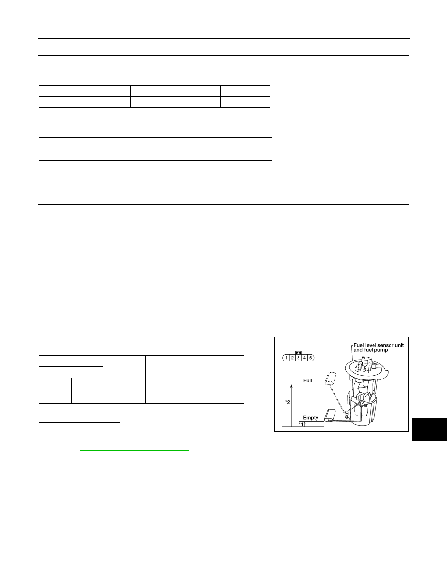
2.
CHECK FUEL LEVEL SENSOR UNIT
Check the resistance between fuel level sensor unit and fuel pump.
*: When float rod is in contact with stopper.
Is inspection result OK?
YES
>> Inspection End.
NO
>> Replace fuel level sensor unit and fuel pump. Refer to
FL-5, "Removal and Installation"
.
Connector
Terminal
Connector
Terminal
Continuity
M24
26
B44
5
Yes
Connector
Terminal
Ground
Continuity
B44
5
No
Terminals
Condition
Resistance (
Ω)
(Approx.)
Height [mm (in)]
Fuel level sensor unit
2
5
Full
*
(2)
91
177 (6.97)
Empty
*
(1)
283
15 (0.59)
LKIA0402E