Nissan Versa Sedan. Instruction - part 501
HRN-6
< REMOVAL AND INSTALLATION >
HORN
REMOVAL AND INSTALLATION
HORN
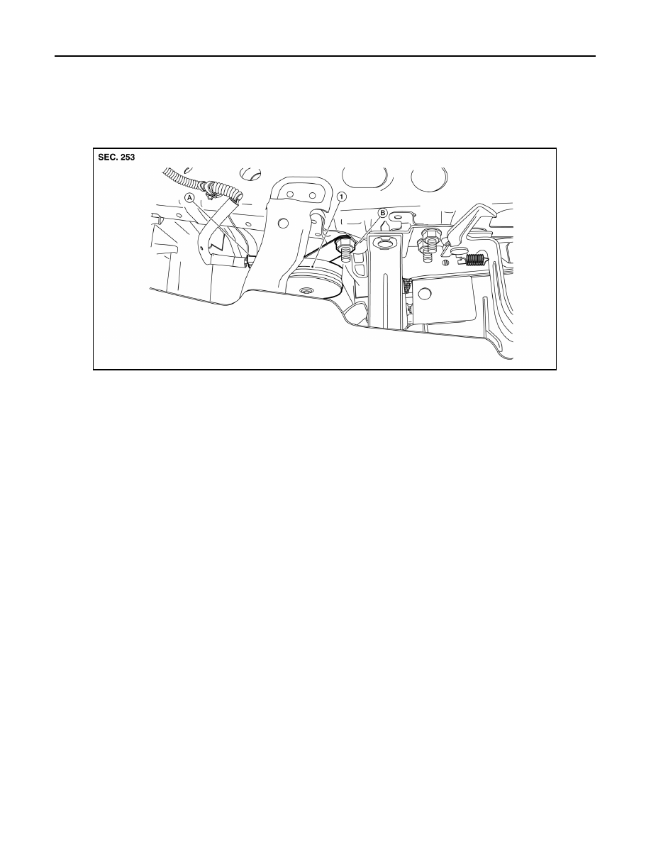
Exploded View
INFOID:0000000009266944
Removal and Installation
INFOID:0000000009266945
REMOVAL
1. Disconnect the harness connectors from the horn.
2. Remove the horn nut and the horn.
INSTALLATION
Installation is in the reverse order of removal.
1. Horn
A. Connector(s)
B. Nut
AWLIA2027ZZ